4-
20
269Plus Motor Management Relay GE Power Management
MEMORY MAP 4 COMMUNICATIONS
4
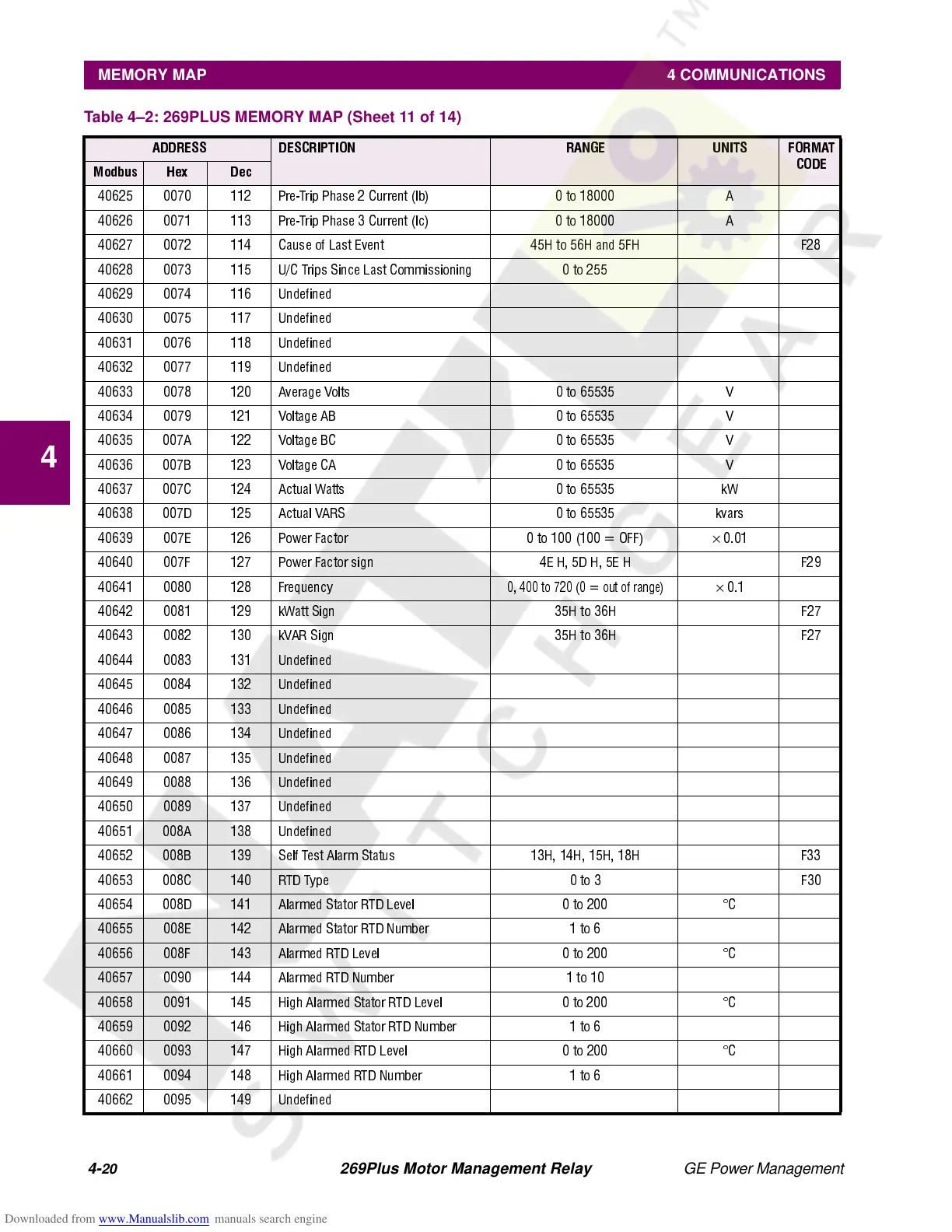
40625 0070 112 Pre-Trip Phase 2 Current (Ib) 0 to 18000 A
40626 0071 113 Pre-Trip Phase 3 Current (Ic) 0 to 18000 A
40627 0072 114 Cause of Last Event 45H to 56H and 5FH F28
40628 0073 115 U/C Trips Since Last Commissioning 0 to 255
40629 007 4 1 16 Undefined
40630 007 5 1 17 Undefined
40631 007 6 1 18 Undefined
40632 007 7 1 19 Undefined
40633 007 8 1 20 Average Volts 0 to 65535 V
40634 007 9 1 21 Voltage AB 0 to 6 5535 V
40635 007 A 122 Voltage BC 0 to 65535 V
40636 00 7B 123 Voltage CA 0 to 65535 V
40637 007C 124 Actual Watts 0 to 65535 kW
40638 007D 125 Actual VARS 0 to 65535 kvars
40639 00 7E 1 26 Power Factor 0 to 100 (100 = OFF )
×
0.01
40640 007F 127 Power Factor sign 4E H, 5D H, 5E H F29
40641 0080 128 Frequency
0, 400 to 720 (0 = out of range)
×
0.1
40642 0081 129 kWatt Sign 35H to 36H F27
40643 0082 130 kVAR Sign 35H to 36H F27
40644 008 3 1 31 Undefined
40645 008 4 1 32 Undefined
40646 008 5 1 33 Undefined
40647 008 6 1 34 Undefined
40648 008 7 1 35 Undefined
40649 008 8 1 36 Undefined
40650 008 9 1 37 Undefined
40651 008 A 138 Undefined
40652 008B 139 Self Test Alarm Status 13H, 14H, 15H, 18H F33
40653 008C 140 RTD Type 0 to 3 F30
40654 008D 141 Alarmed Stator RTD Level 0 to 200 °C
40655 008E 142 Alarmed Stator RTD Number 1 to 6
40656 008F 143 Alarmed RTD Level 0 to 200 °C
40657 0090 144 Alarmed RTD Number 1 to 10
40658 0091 145 High Alarmed Stator RTD Level 0 to 200 °C
40659 0092 146 High Alarmed Stator RTD Number 1 to 6
40660 0093 147 High Alarmed RTD Level 0 to 200 °C
40661 0094 148 High Alarmed RTD Number 1 to 6
40662 009 5 1 49 Undefined
Table 4–2: 269PLUS MEMORY MAP (Sheet 11 of 14)
ADDRESS DESCRIPTION RANGE UNITS FORMAT
CODE
Modbus Hex Dec