GE Power Management 269Plus Motor Management Relay 1-
7
1 INTRODUCTION TECHNICAL SPECIFICATIONS
1
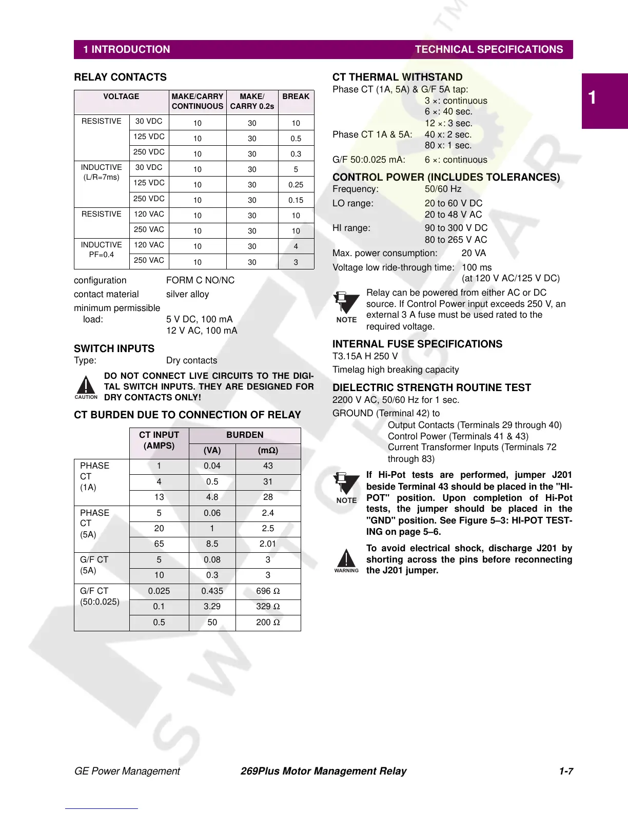
RELAY CONTACTS
configuration FORM C NO/NC
contact material silver alloy
minimum permissible
load: 5 V DC, 100 mA
12 V AC, 100 mA
SWITCH INPUTS
Type: Dry contacts
DO NOT CONNECT LIVE CIRCUITS TO THE DIGI-
TAL SWITCH INPUTS. THEY ARE DESIGNED FOR
DRY CONTACTS ONLY!
CT BURDEN DUE TO CONNECTION OF RELAY
CT THERMAL WITHSTAND
Phase CT (1A, 5A) & G/F 5A tap:
3 ×: continuous
6×:40sec.
12 ×: 3 sec.
Phase CT 1A & 5A: 40 x: 2 sec.
80 x: 1 sec.
G/F 50:0.025 mA: 6 ×: continuous
CONTROL POWER (INCLUDES TOLERANCES)
Frequency: 50/60 Hz
LO range: 20 to 60 V DC
20 to 48 V AC
HI range: 90 to 300 V DC
80 to 265 V AC
Max. power consumption: 20 VA
Voltage low ride-through time: 100 ms
(at 120 V AC/125 V DC)
Relay can be powered from either AC or DC
source. If Control Power input exceeds 250 V, an
external 3 A fuse must be used rated to the
required voltage.
INTERNAL FUSE SPECIFICATIONS
T3.15A H 250 V
Timelag high breaking capacity
DIELECTRIC STRENGTH ROUTINE TEST
2200 V AC, 50/60 Hz for 1 sec.
GROUND (Terminal 42) to
Output Contacts (Terminals 29 through 40)
Control Power (Terminals 41 & 43)
Current Transformer Inputs (Terminals 72
through 83)
If Hi-Pot tests are performed, jumper J201
beside Terminal 43 should be placed in the "HI-
POT" position. Upon completion of Hi-Pot
tests, the jumper should be placed in the
"GND" position. See Figure 5–3: HI-POT TEST-
ING on page 5–6.
To avoid electrical shock, discharge J201 by
shorting across the pins before reconnecting
theJ201jumper.
VOLTAGE MAKE/CARRY
CONTINUOUS
MAKE/
CARRY 0.2s
BREAK
RESISTIVE 30 VDC
10 30 10
125 VDC
10 30 0.5
250 VDC
10 30 0.3
INDUCTIVE
(L/R=7ms)
30 VDC
10 30 5
125 VDC
10 30 0.25
250 VDC
10 30 0.15
RESISTIVE 120 VAC
10 30 10
250 VAC
10 30 10
INDUCTIVE
PF=0.4
120 VAC
10 30 4
250 VAC
10 30 3
CT INPUT
(AMPS)
BURDEN
(VA) (mΩ
ΩΩ
Ω)
PHASE
CT
(1A)
10.0443
40.531
13 4.8 28
PHASE
CT
(5A)
5 0.06 2.4
20 1 2.5
65 8.5 2.01
G/F CT
(5A)
50.08 3
10 0.3 3
G/F CT
(50:0.025)
0.025 0.435 696 Ω
0.1 3.29 329 Ω
0.5 50 200 Ω
CAUTION
NOTE
NOTE