GE Power Management 269Plus Motor Management Relay 3-
27
3 SETUP AND USE SETPOINTS MODE
3
SETPOINTS PAGE 5: SYSTEM CONFIGURATION
51
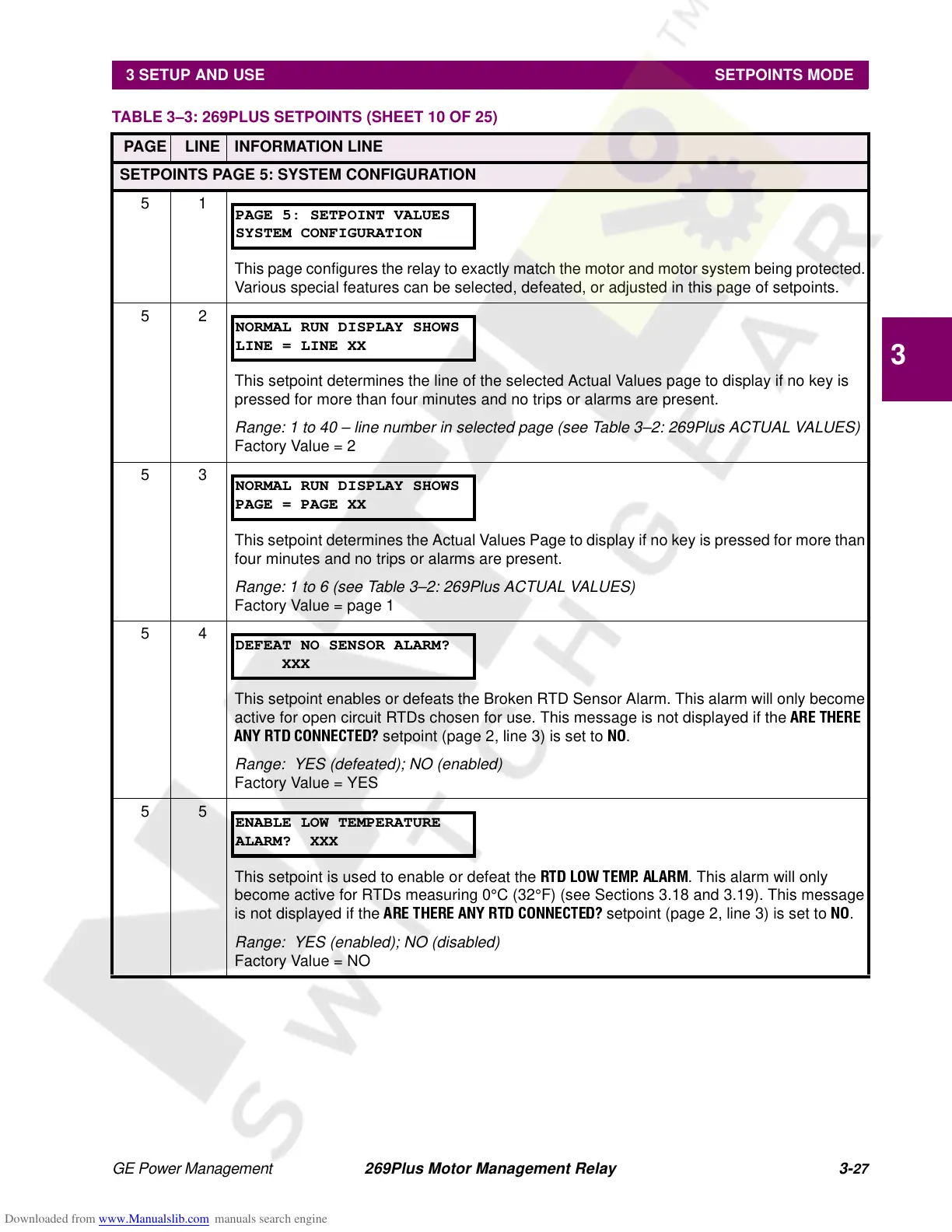
This page configures the relay to exactly match the motor and motor system being protected.
Various special features can be selected, defeated, or adjusted in this page of setpoints.
52
This setpoint determines the line of the selected Actual Values page to display if no key is
pressed for more than four minutes and no trips or alarms are present.
Range: 1 to 40 – line number in selected page (see Table 3–2: 269Plus ACTUAL VALUES)
Factory Value = 2
53
This setpoint determines the Actual Values Page to display if no key is pressed for more than
four minutes and no trips or alarms are present.
Range: 1 to 6 (see Table 3–2: 269Plus ACTUAL VALUES)
Factory Value = page 1
54
This setpoint enables or defeats the Broken RTD Sensor Alarm. This alarm will only become
active for open circuit RTDs chosen for use. This message is not displayed if the
ARE THERE
ANY RTD CONNECTED?
setpoint (page 2, line 3) is set to
NO
.
Range: YES (defeated); NO (enabled)
Factory Value = YES
55
This setpoint is used to enable or defeat the
RTD LOW TEMP. ALARM
. This alarm will only
become active for RTDs measuring 0°C(32°F) (see Sections 3.18 and 3.19). This message
is not displayed if the
ARE THERE ANY RTD CONNECTED?
setpoint (page 2, line 3) is set to
NO
.
Range: YES (enabled); NO (disabled)
Factory Value = NO
TABLE 3–3: 269PLUS SETPOINTS (SHEET 10 OF 25)
PAGE LINE INFORMATION LINE
PAGE 5: SETPOINT VALUES
SYSTEM CONFIGURATION
NORMAL RUN DISPLAY SHOWS
LINE = LINE XX
NORMAL RUN DISPLAY SHOWS
PAGE = PAGE XX
DEFEAT NO SENSOR ALARM?
XXX
ENABLE LOW TEMPERATURE
ALARM? XXX