GE Power Management 269Plus Motor Management Relay 3-
31
3 SETUP AND USE SETPOINTS MODE
3
519
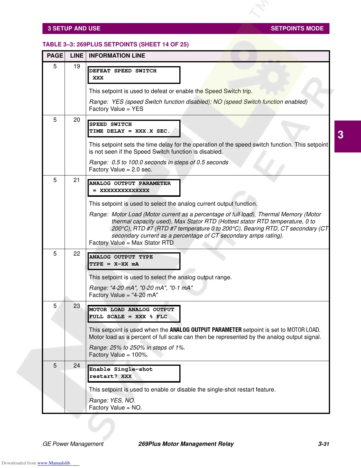
This setpoint is used to defeat or enable the Speed Switch trip.
Range: YES (speed Switch function disabled); NO (speed Switch function enabled)
Factory Value = YES
520
This setpoint sets the time delay for the operation of the speed switch function. This setpoint
is not seen if the Speed Switch function is disabled.
Range: 0.5 to 100.0 seconds in steps of 0.5 seconds
Factory Value = 2.0 sec.
521
This setpoint is used to select the analog current output function.
Range: Motor Load (Motor current as a percentage of full load), Thermal Memory (Motor
thermal capacity used), Max Stator RTD (Hottest stator RTD temperature, 0 to
200°C), RTD #7 (RTD #7 temperature 0 to 200°C), Bearing RTD, CT secondary (CT
secondary current as a percentage of CT secondary amps rating).
Factory Value = Max Stator RTD
522
This setpoint is used to select the analog output range.
Range: "4-20 mA", "0-20 mA", "0-1 mA"
Factory Value = "4-20 mA"
523
This setpoint is used when the
ANALOG OUTPUT PARAMETER
setpoint is set to
MOTOR LOAD
.
Motor load as a percent of full scale can then be represented by the analog output signal.
Range: 25% to 250% in steps of 1%.
Factory Value = 100%.
524
This setpoint is used to enable or disable the single-shot restart feature.
Range: YES, NO.
Factory Value = NO.
TABLE 3–3: 269PLUS SETPOINTS (SHEET 14 OF 25)
PAGE LINE INFORMATION LINE
DEFEAT SPEED SWITCH
XXX
SPEED SWITCH
TIME DELAY = XXX.X SEC.
ANALOG OUTPUT PARAMETER
= XXXXXXXXXXXXXX
ANALOG OUTPUT TYPE
TYPE = X-XX mA
MOTOR LOAD ANALOG OUTPUT
FULL SCALE = XXX % FLC
Enable Single-shot
restart? XXX