GE Power Management 269Plus Motor Management Relay 3-
33
3 SETUP AND USE SETPOINTS MODE
3
529
This setpoint appears only if the relay is a drawout. Entering value from factory for this
setpoint allows access of the failsafe codes for approximately 3 minutes.
FOR PROPER OPERATION OF A DRAWOUT UNIT, HARDWARE CHANGES MAY
BE REQUIRED IF THE FAILSAFE CODE IS CHANGED (CONTACT FACTORY).
Factory Value = 0
530
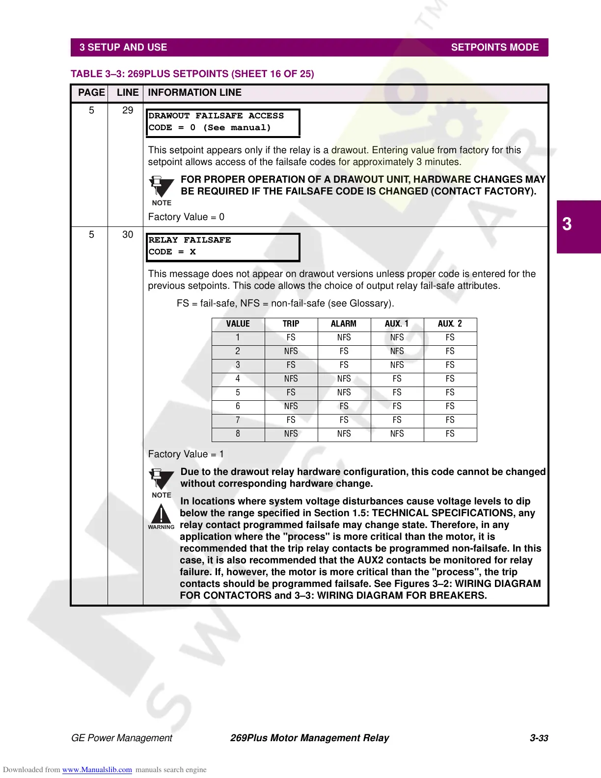
This message does not appear on drawout versions unless proper code is entered for the
previous setpoints. This code allows the choice of output relay fail-safe attributes.
FS = fail-safe, NFS = non-fail-safe (see Glossary).
Factory Value = 1
Due to the drawout relay hardware configuration, this code cannot be changed
without corresponding hardware change.
In locations where system voltage disturbances cause voltage levels to dip
below the range specified in Section 1.5: TECHNICAL SPECIFICATIONS, any
relay contact programmed failsafe may change state. Therefore, in any
application where the "process" is more critical than the motor, it is
recommended that the trip relay contacts be programmed non-failsafe. In this
case, it is also recommended that the AUX2 contacts be monitored for relay
failure. If, however, the motor is more critical than the "process", the trip
contacts should be programmed failsafe. See Figures 3–2: WIRING DIAGRAM
FOR CONTACTORS and 3–3: WIRING DIAGRAM FOR BREAKERS.
TABLE 3–3: 269PLUS SETPOINTS (SHEET 16 OF 25)
PAGE LINE INFORMATION LINE
DRAWOUT FAILSAFE ACCESS
CODE = 0 (See manual)
NOTE
RELAY FAILSAFE
CODE = X
VALUE TRIP ALARM AUX. 1 AUX. 2
1 FS NFS NFS FS
2 NFS FS NFS FS
3 FS FS NFS FS
4 NFS NFS FS FS
5 FS NFS FS FS
6 NFS FS FS FS
7 FSFSFSFS
8 NFS NFS NFS FS
NOTE
ARNIN