GE Power Management 269Plus Motor Management Relay 3-
35
3 SETUP AND USE SETPOINTS MODE
3
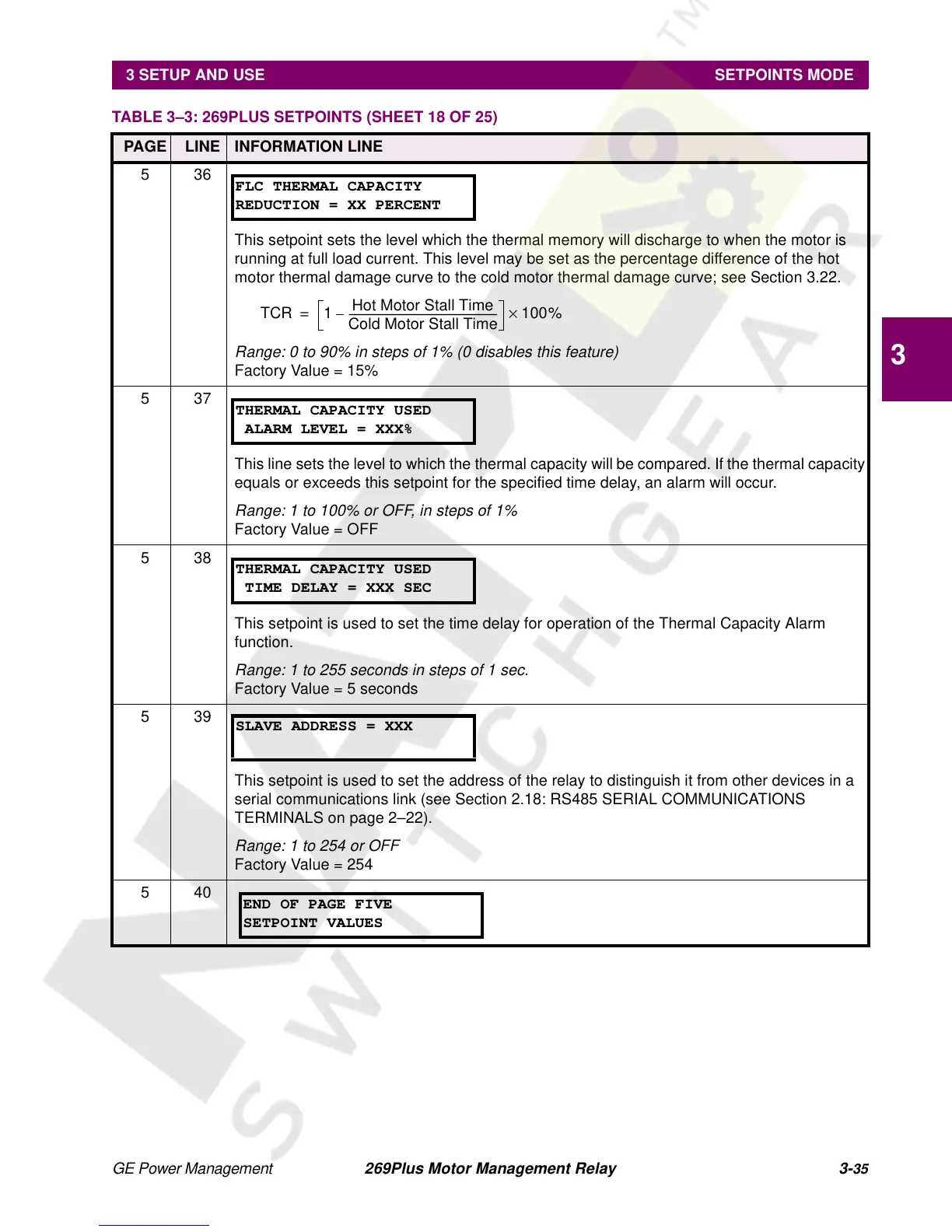
536
This setpoint sets the level which the thermal memory will discharge to when the motor is
running at full load current. This level may be set as the percentage difference of the hot
motor thermal damage curve to the cold motor thermal damage curve; see Section 3.22.
Range: 0 to 90% in steps of 1% (0 disables this feature)
Factory Value = 15%
537
This line sets the level to which the thermal capacity will be compared. If the thermal capacity
equals or exceeds this setpoint for the specified time delay, an alarm will occur.
Range: 1 to 100% or OFF, in steps of 1%
Factory Value = OFF
538
This setpoint is used to set the time delay for operation of the Thermal Capacity Alarm
function.
Range: 1 to 255 seconds in steps of 1 sec.
Factory Value = 5 seconds
539
This setpoint is used to set the address of the relay to distinguish it from other devices in a
serial communications link (see Section 2.18: RS485 SERIAL COMMUNICATIONS
TERMINALSonpage2–22).
Range: 1 to 254 or OFF
Factory Value = 254
540
TABLE 3–3: 269PLUS SETPOINTS (SHEET 18 OF 25)
PAGE LINE INFORMATION LINE
FLC THERMAL CAPACITY
REDUCTION = XX PERCENT
TCR 1
Hot Motor Stall Time
Cold Motor Stall Time
---------------------------------------------------------– 100%×=
THERMAL CAPACITY USED
ALARM LEVEL = XXX%
THERMAL CAPACITY USED
TIME DELAY = XXX SEC
SLAVE ADDRESS = XXX
END OF PAGE FIVE
SETPOINT VALUES