When using two UV monitors, the signal from the first UV monitor is by default used for peak
fractionation. This can be changed by editing the text instruction Fraction Collection:Peak
fractionation parameters:Signal source and choosing UV 2nd as Signal source.
Note:
When using two UV monitors with different cell lengths to increase the UV absorption dynamic
range, the U9-L signal comes from the real cell length and has to be calibrated for exact calcu-
lations. The U9-M signal is automatically calibrated to nominal cell length.
Note:
UV monitor U9-L, 2nd can be located anywhere in the flow path and is therefore shown in the Process
Picture in UNICORN as a component without a fixed place. This means that it is possible to place U9-
L, 2nd before the other UV monitor in the flow path.
If U9-L 2nd is placed on the high pressure side of the column, pressure limits have to be con-
sidered. See UV monitor options, on page 416
Note:
Connect tubing
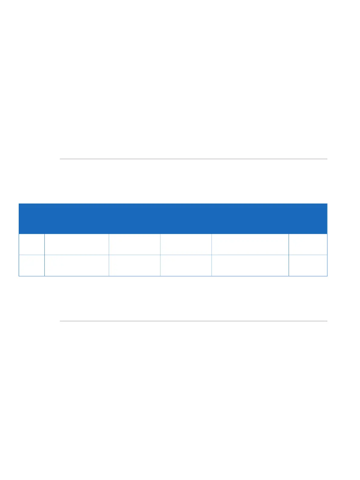
The table below shows the tubing and connectors to be used with UV monitor U9-L.
If a second UV monitor is used, the tubing for this has to be cut manually.
Note:
Tubing
length
(mm)
ConnectorTubingConnectionTubing
label
ÄKTA pure 150ÄKTA pure 25
160Fingertight connector,
1/16"
PEEK, o.d. 1/16",
i.d. 0.75 mm
PEEK, o.d. 1/16",
i.d. 0.50 mm
Tubing to
UV monitor U9-L
6
170Fingertight connector,
1/16"
PEEK, o.d. 1/16",
i.d. 0.75 mm
PEEK, o.d. 1/16",
i.d. 0.50 mm
Tubing from
UV monitor U9-L
7
To perform a run with the flow in reverse direction through UV monitor U9-L, a longer tubing
7 is needed. Replace the 170 mm tubing from the UV monitor with tubing that is 210 mm long
and adjust the delay volume accordingly. For example, changing from 170 mm to 210 mm for
0.5 mm i.d. tubing increases the delay volume with 8 µl.
Note:
72 ÄKTA pure User Manual 29119969 AB
2 The ÄKTA pure instrument
2.4 Instrument modules
2.4.13 UV monitors