EasyManuals Logo

GE LOGIQ E10 Service Manual

GE LOGIQ E10
778 pages
To Next Page IconTo Next Page
To Previous Page IconTo Previous Page
Page #292 background imageLoading...
Page #292 background image
DIRECTION 5750007-1EN, REV. 1 LOGIQ E10 BASIC SERVICE MANUAL
8 - 46 Section 8-6 - Replacing Covers and Bumpers
Rear Cover/Air Exhaust removal
The Rear Cover is attached to the LOGIQ E10 with four self-tapping screws, two on each side. These
mounting screws are screwed into plastic. Use care during installation, DO NOT overtighten.
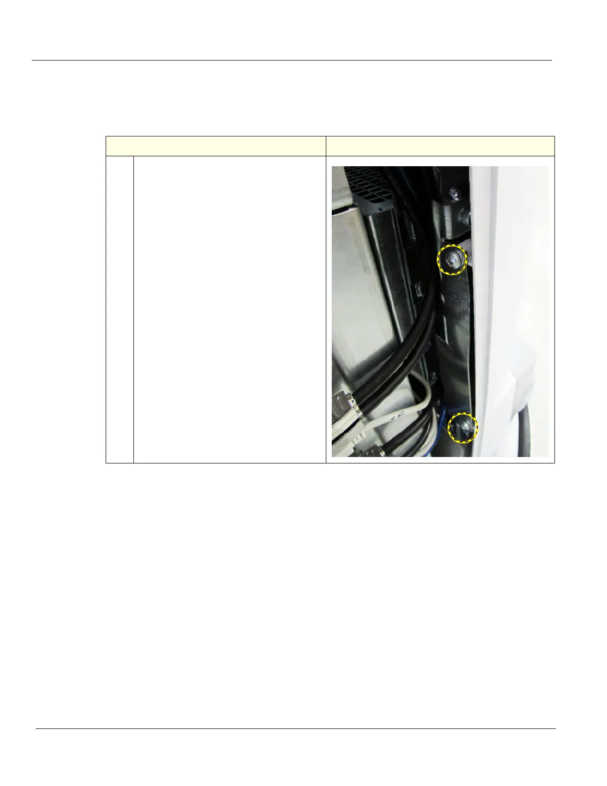
Table 8-42 Rear Cover/Air Exhaust removal
Steps
Corresponding Graphic
1. Remove the two Phillips screws on each
side of the Rear Cover that secure the rear
cover to the Frame.
Lift the Rear Cover away.

Table of Contents

Other manuals for GE LOGIQ E10

Questions and Answers:

Question and Answer IconNeed help?

Do you have a question about the GE LOGIQ E10 and is the answer not in the manual?

GE LOGIQ E10 Specifications

General IconGeneral
TouchscreenYes
3D/4D ImagingYes
ApplicationsVascular, Cardiac, Musculoskeletal, OB/GYN
Image StorageUSB, Network
ConnectivityDICOM, Ethernet, Wireless

Related product manuals