EasyManuals Logo

GE LOGIQ E10 Service Manual

GE LOGIQ E10
778 pages
To Next Page IconTo Next Page
To Previous Page IconTo Previous Page
Page #333 background imageLoading...
Page #333 background image
DIRECTION 5750007-1EN, REV. 1 LOGIQ E10 BASIC SERVICE MANUAL
Chapter 8 Replacement Procedures 8 - 87
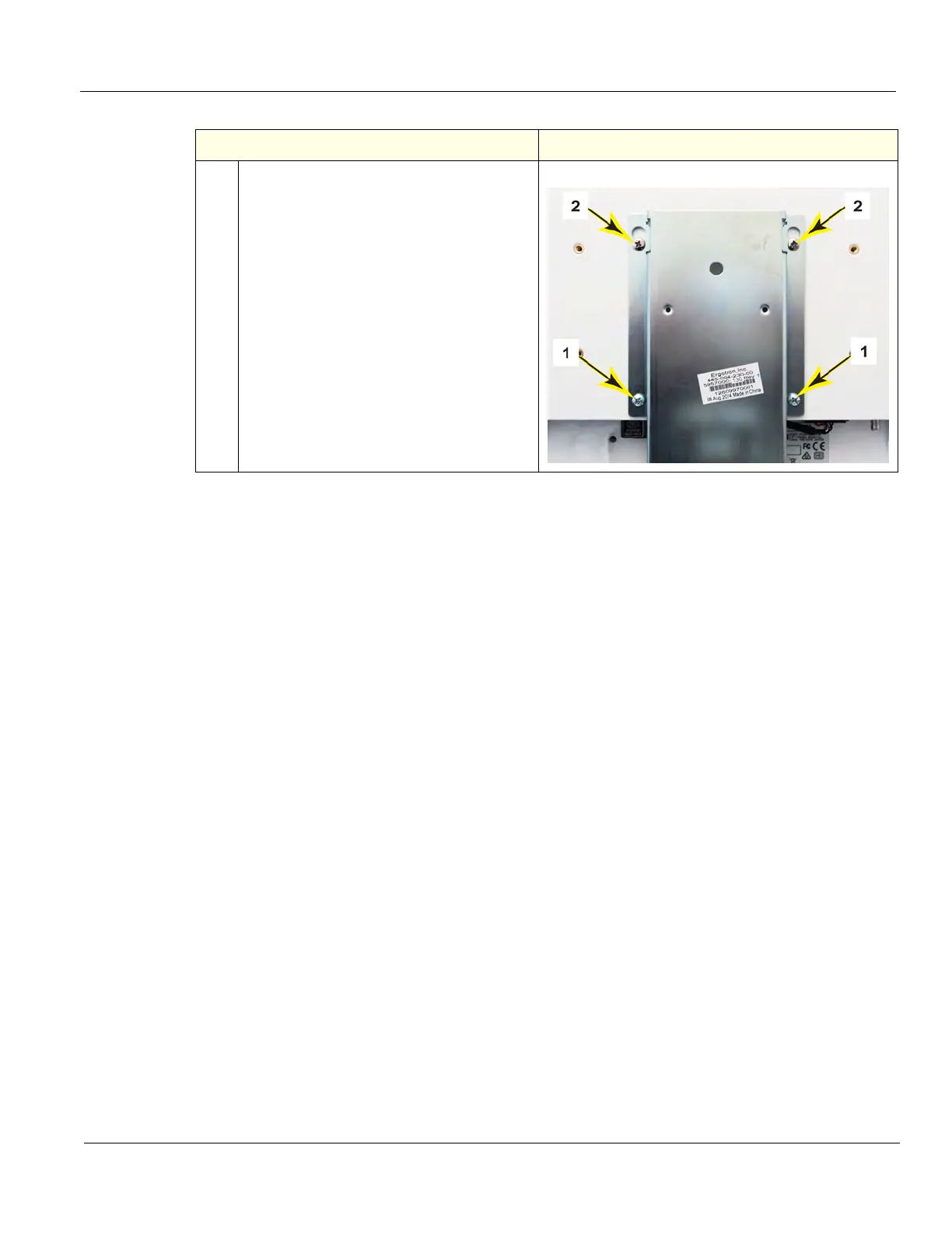
4.
Remove the two lower Phillips screws (1).
Loosen the upper Phillips screws (2). The
Monitor will be supported by the two upper
screws.
Slide the Monitor off of the Arm Assembly.
Remove the upper Phillips screws to
re-install into the replacement Monitor.
Monitor mounting screws and holes
Table 8-102 Main Monitor removal
Steps Corresponding Graphic

Table of Contents

Other manuals for GE LOGIQ E10

Questions and Answers:

Question and Answer IconNeed help?

Do you have a question about the GE LOGIQ E10 and is the answer not in the manual?

GE LOGIQ E10 Specifications

General IconGeneral
TouchscreenYes
3D/4D ImagingYes
ApplicationsVascular, Cardiac, Musculoskeletal, OB/GYN
Image StorageUSB, Network
ConnectivityDICOM, Ethernet, Wireless

Related product manuals