DIRECTION 5750007-1EN, REV. 1 LOGIQ E10 BASIC SERVICE MANUAL
Chapter 8 Replacement Procedures 8 - 103
Monitor Arm Assembly Adapter installation
Table 8-113 Arm Adapter installation
Steps Corresponding Graphic
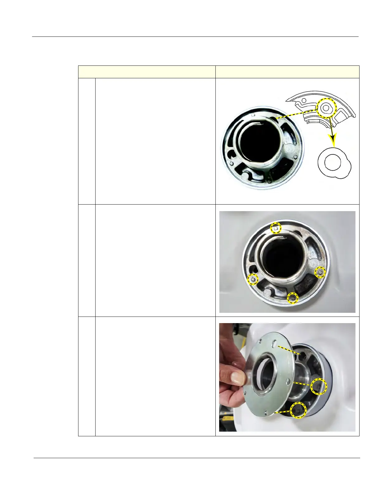
1.
NOTE: Note the shape of the REAR
mounting hole, this is important for when
the UI Boss Bearing is installed.
(rear of LOGIQ E10)
(OP, front of LOGIQ E10)
2.
Insert the Adapter into the Upper UI Frame
with the rear mounting hole at the rear.
Align the mounting holes and install the two
M5 x 50 screws using a 4 mm hex wrench
to secure the Adapter. Torque 2.5 Nm (1.8
lbf-ft {21.6 lbf-in}).
NOTE: Note the four bosses on the
Adapter Bearing surface, these capture
and position the Bearing when it is
installed.
3.
NOTE: MAKE SURE the REAR mounting
hole for the Arm Neck Lock Pin, in the
Bearing is aligned with the REAR mounting
hole and the four bosses of the Adapter
capture and position the Bearing.
The Bearing should seat firmly on the
Adapter. If the Bearing “rocks“, it is NOT
installed correctly.