DIRECTION 5750007-1EN, REV. 1 LOGIQ E10 BASIC SERVICE MANUAL
8 - 104 Section 8-7 - Replacing Top Console Parts
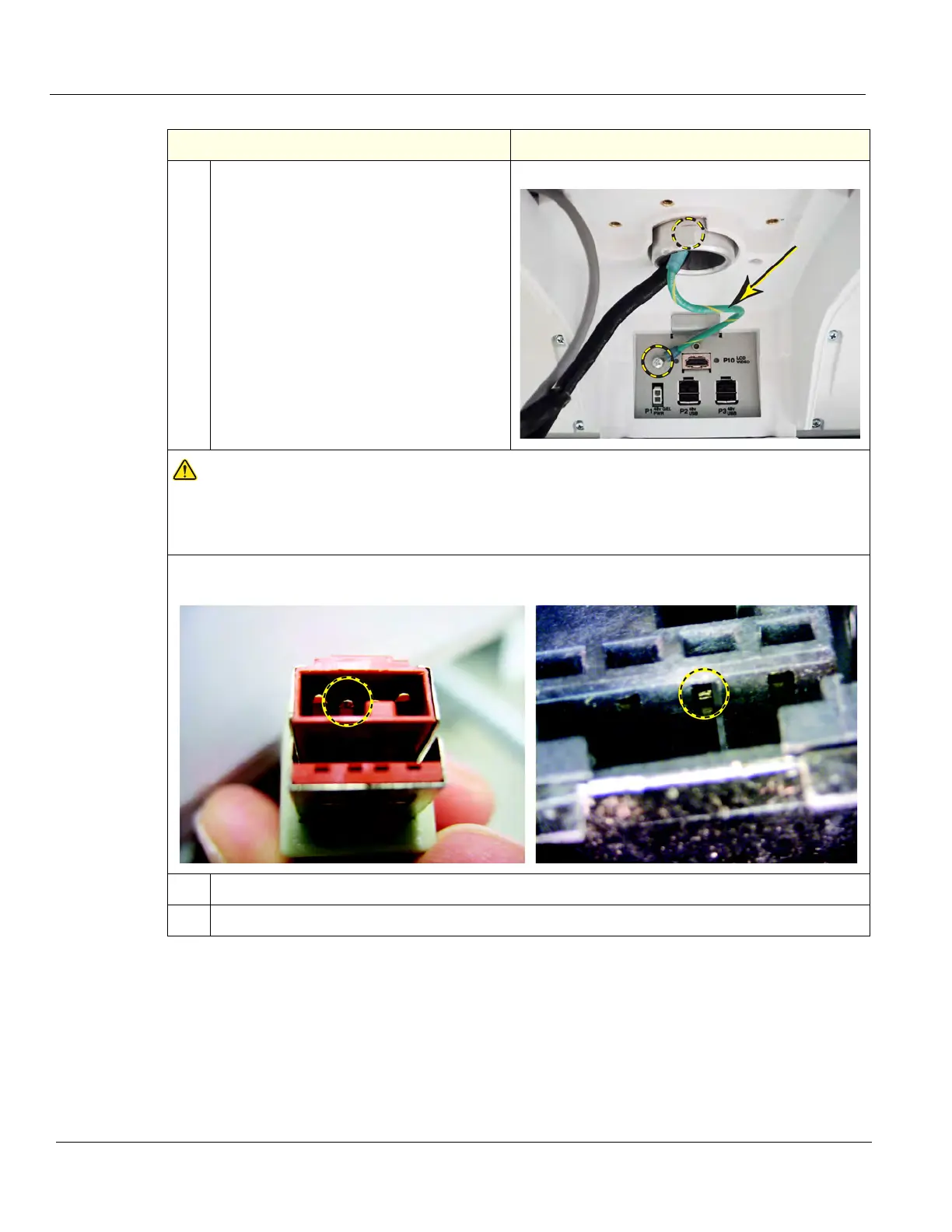
4.
Install the Ground Cable to the Adapter
inside the Adapter, using the screw and
lock washer removed. Torque 1.3 Nm (0.96
lbf-ft {11.5 lbf-in}).
NOTICE
DO NOT connect the Monitor power cable to the power (P2) or (P3) connector on the Bulkhead
when the LOGIQ E10 is powered up. Damage to the Monitor Power Cable and/or the Bulkhead
Board can occur. See: images below of damage that can occur.
48VDC pin in the P3 connector (center pin), shows damage.
The outside two pins are Ground. Cable left, Bulkhead Connector right.
5.
Re-install Monitor and Arm Assembly and connect the Monitor Cables.
6.
Re-install all Covers removed.
Table 8-113 Arm Adapter installation
Steps Corresponding Graphic