DIRECTION 5750007-1EN, REV. 1 LOGIQ E10 BASIC SERVICE MANUAL
Chapter 8 Replacement Procedures 8 - 129
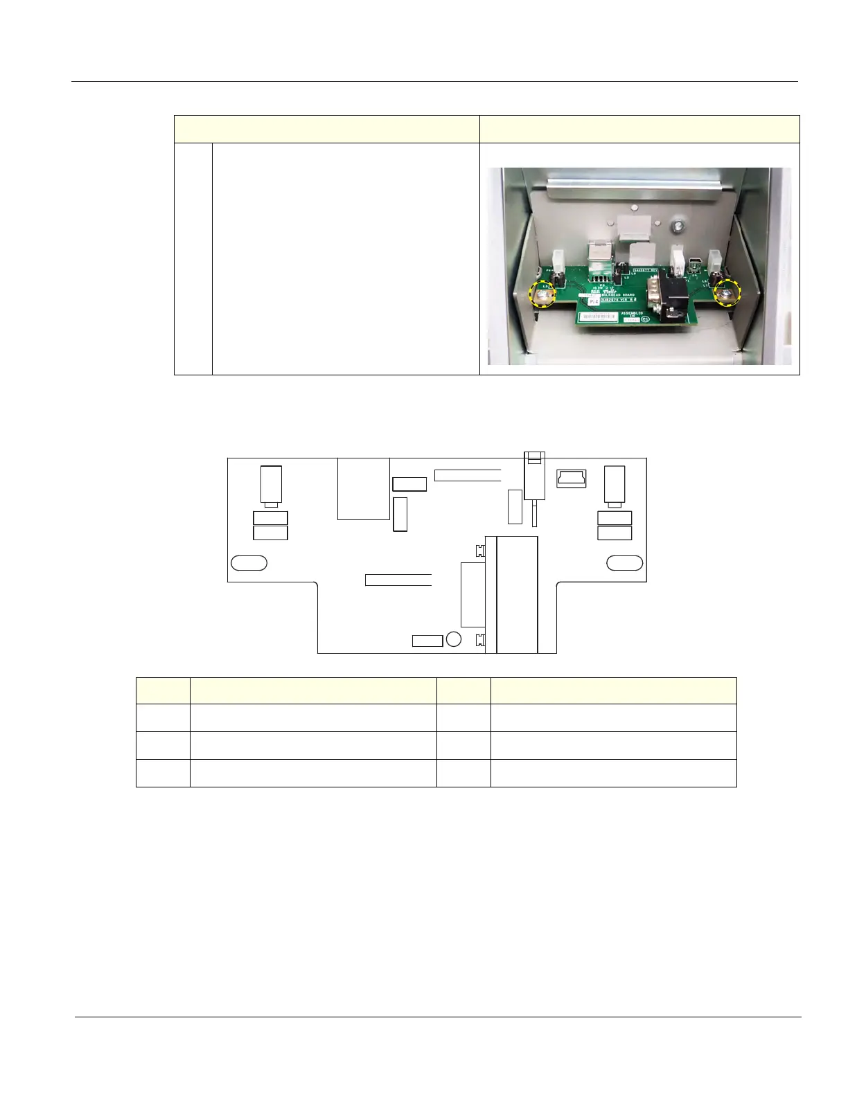
Bulkhead Board installation
3. Remove the two Bulkhead Board
grounding screws ad washers, using a #1
Phillips screwdriver.
Note how the board is installed under the
two tabs, slide the Bulkhead Board out.
Figure 8-3 Bulkhead assembly cable placement
Item Connection Item Connection
P5, P6
Speakers P5 (right) and P6 (left)
P8
USB Upper OP
P3
Power / USB to Monitor
P4
Power from Backplane
P1
Gel Warmer, if present
Table 8-147 Bulkhead Board removal
Steps Corresponding Graphic
L5
L4
L2
L9
L3
L7
L6
5482676
ASSEMBLED
VER
IN
B
PWA
e
5482677
1
REV
PWB
3
2
BULKHEAD BOARD
P6 P5
P3
P4
P8
P1