DIRECTION 5750007-1EN, REV. 1 LOGIQ E10 BASIC SERVICE MANUAL
8 - 146 Section 8-7 - Replacing Top Console Parts
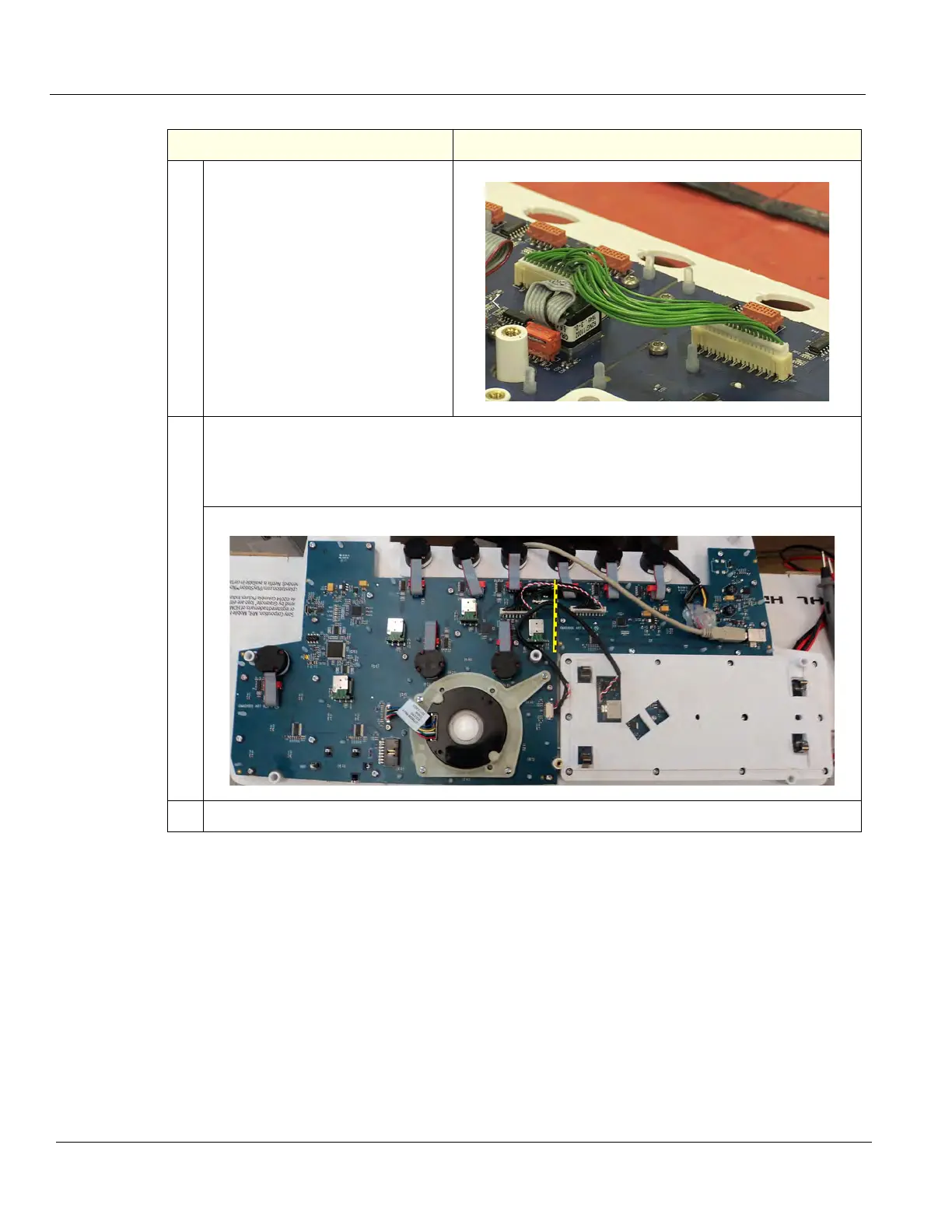
4. There are two separate boards.
Disconnect one end of the Signal
Cable between the two boards.
Make sure the Keyboard cable has
been disconnected.
It is not necessary to disconnect the
remaining cables.
5. Remove the 30 screws securing the boards to the Bezel, using a T10 Torx driver. KEEP the old
Bezel facing down.
There are 22 screws on Trackball board and 8 on the other board. (Complete board shown for
reference.)
6. Remove the boards and transfer the Op Panel controls the new Bezel, one at a time.
Table 8-167 Lower Bezel removal
Steps Corresponding Graphic