DIRECTION 5750007-1EN, REV. 1 LOGIQ E10 BASIC SERVICE MANUAL
8 - 150 Section 8-7 - Replacing Top Console Parts
Lower Op Encoders/Joysticks
The four Mode Select (Concentric Shaft) Encoders adjust the M-mode, PW-mode, CF-Mode, and B-
Mode scans.
NOTE: This procedure you will essentially perform the same procedure as replacing the Lower Op
Bezel, except, DO NOT remove the:
• Six Encoders for the Upper OP/Touch Panel.
• Silicone Keyboard Cover and Keyboard Mechanics.
• Keyboard Board side circuit board.
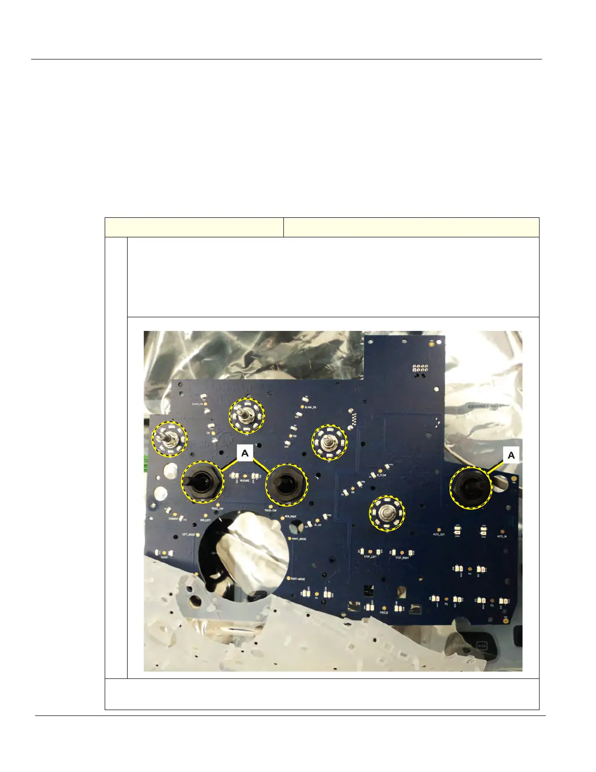
Table 8-173 Lower Op Encoders and Encoders/Joysticks replacement
Steps Corresponding Graphic
1. Fold back the elastomer to expose the nuts that secure the Encoders/Joysticks to the Lower
Switch and Encoder Board.
Mode Encoders circled - Use a 7/16 inch, deep socket wrench or 7/16 inch open-ended wrench
to loosen the nut(s).
Encoders/Joysticks (A) - use a 24 mm socket or an adjustable wrench and remove the nut(s).
Remove Encoder(s)/Joystick(s) as necessary.
Continued