DIRECTION 5750007-1EN, REV. 1 LOGIQ E10 BASIC SERVICE MANUAL
8 - 172 Section 8-7 - Replacing Top Console Parts
Calibration and adjustments
No calibrations or adjustments are needed after this part replacement.
Verification
Perform the following steps to verify that the product is functioning as intended after this replacement:
1.) Verify that all screws removed earlier have been installed.
2.) Connect cables and Probes removed earlier.
3.) Power up the system to verify that it operates as intended.
4.) If a Gel Warmer is installed in the Options Holder, see: additional Verification and Functional
Checks for Gel Warmer (see: 8-7-23 "Gel Warmer replacement" on page 8-173).
Functional Checks
Perform the following functional checks to confirm the system is operational before returning the system
to the customer.
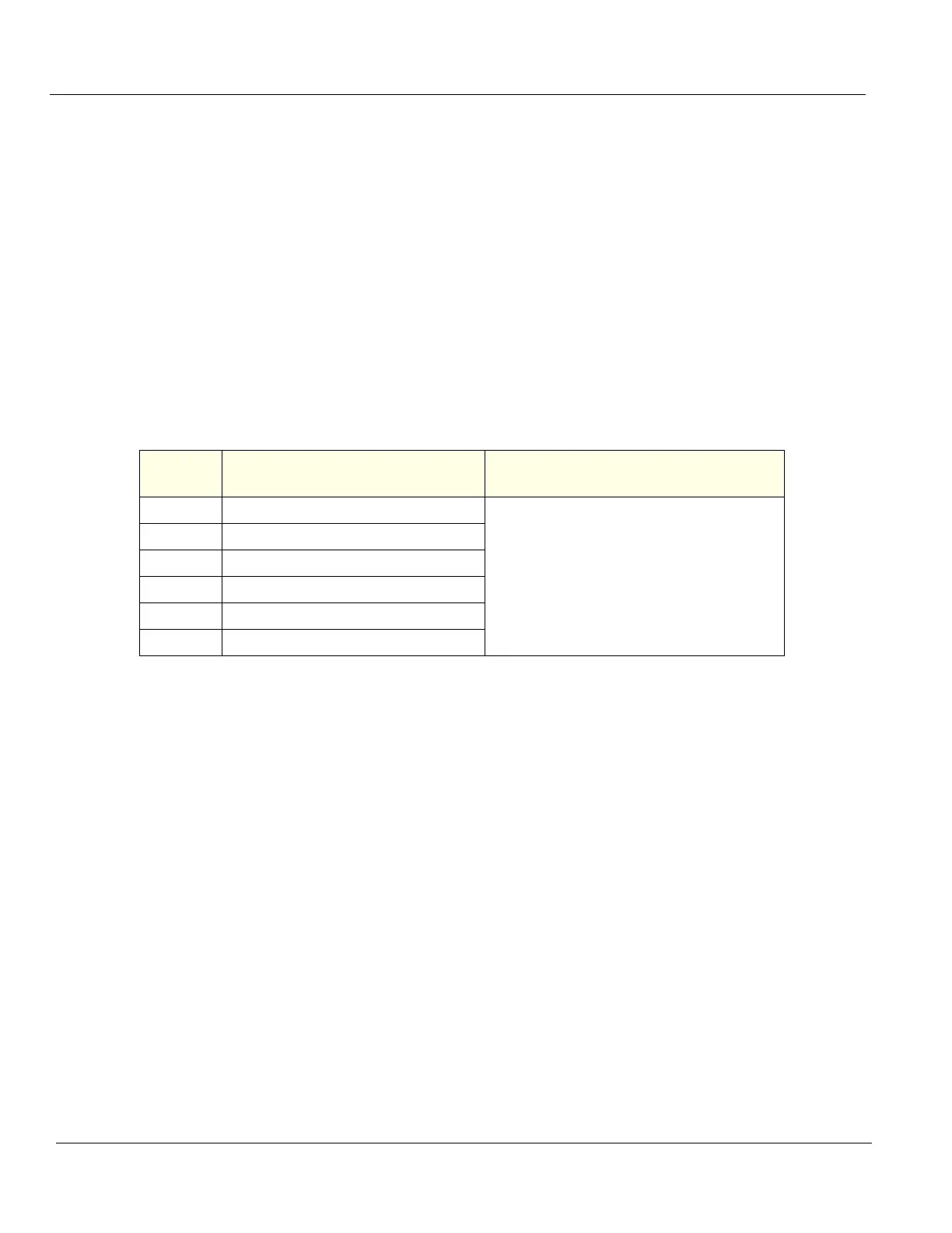
Table 8-203 Options Holder / Left or Right Support replacement Functional Checks
See:
Section Functional Check Debrief Script
4-2-3 Power ON/Boot Up
LOGIQ E10 Basic Service Manual, Direction
5750007-1EN, Rev. 1. Equipment passed all
required checks and is ready for use.
4-2-7 Probe/Connectors Checks
4-2-7 B-Mode Checks
4-2-7 System CFM and PWD Checks
4-2-7 Basic Measurements
4-2-4 Power SHUT DOWN