DIRECTION 5750007-1EN, REV. 1 LOGIQ E10 BASIC SERVICE MANUAL
Chapter 8 Replacement Procedures 8 - 201
Z-Mechanism removal
Table 8-230 Z-Mechanism removal
Step Corresponding Graphic
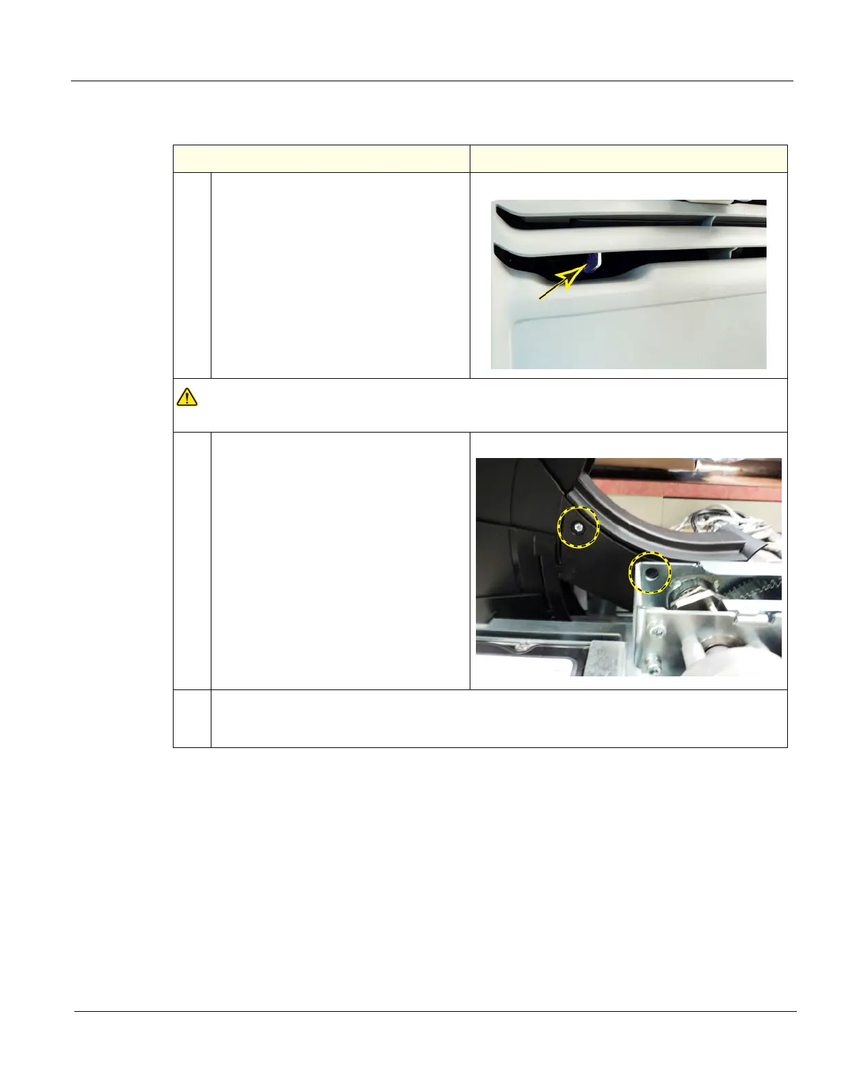
1.
The operator console can drop
unexpectedly when the Z-Mechanism is
released or bumped while working near
this and the Back Cover is off.
Be aware of this if the Z-Mech has
become warn or has weakened.
If you suspect the Z-Mech is warn or has
weakened, it should be replaced.
Z-Mechanism Manual release lever
WARNINGWARNING
Operator console can drop unexpectedly when the mechanism is released.
2.
Remove the four screws securing the
Main Cable Cover and the Column Cover,
using a #2 Phillips screw driver.
Support the Column Cover when the
screws are removed so the Cover does
not fall.
The right side, rear screw can be
accessed through the hole in the Drive
Gear housing.
3. Take note on how the Cables are routed, they MUST BE returned to the same location.
Remove the screws securing the Ground P-clamp, (A) Cable Clamps (B) and the
screw (C) securing the XYZ Motor Controller, using a #2 Phillips screw driver.