DIRECTION 5750007-1EN, REV. 1 LOGIQ E10 BASIC SERVICE MANUAL
8 - 202 Section 8-8 - Replacing XYZ Parts
4. Disconnect all of the Main Cable Harness connections from the ECB - ECB J5, ECB J6,
ECB J15 and MOTOR CTRL (Button Interface), and power from BACKPLANE J12.
5. Disconnect the remaining cabling to the XYZ Motor Controller, USB Interface, Lock Motor
Z motor, Brakes and remove the grounds cables.
If the Brake Cable are not identified (left / right), mark them to ensure they are connected
correctly later.
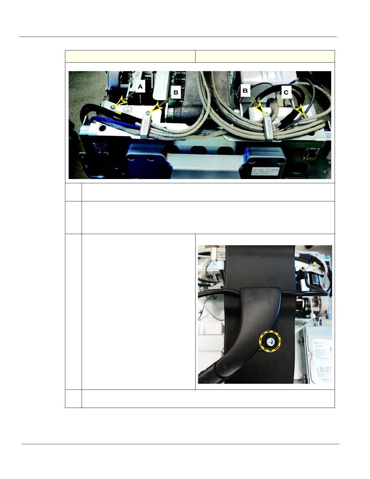
6. Remove the Main Cable Harness from the
top of the Z-Mech, using a 5 mm hex
wrench.
Note how the XY-Mech Brake cables are
routed.
Feed all the cables through the Z-Mech.
7. Remove the screws (D) securing the right and left Cable Harness Brackets, using a 4 mm hex
wrench.
Table 8-230 Z-Mechanism removal
Step Corresponding Graphic