DIRECTION 5750007-1EN, REV. 1 LOGIQ E10 BASIC SERVICE MANUAL
Chapter 8 Replacement Procedures 8 - 205
Z-Mechanism installation
Table 8-231 Z-Mechanism installation
Step Corresponding Graphic
1. Position the Z-Mech, so the holes for the fixing screws align.
Re-install the right and left Cable Harness Brackets and the five Countersunk screws, DO NOT
tighten.
Re-install the remaining six screws and washers, DO NOT tighten.
Torque top five screws to 10 Nm {7.4 lbf-ft}) and the six screws to screws 10 Nm
{7.4 lbf-ft}).
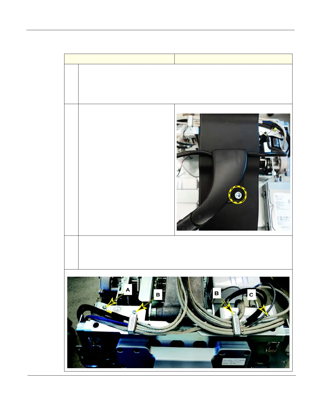
2. Make sure the XY-Mech Brake cables are
going to the correct Brakes and re-install
the Main Cable Harness to the Z-Mech
and XY-Mech. Torque to
1.5 Nm +/-10%.
3. The Cables MUST BE returned to the same location and channeled under the Cable Cover.
Re-install the screws to secure the Ground P-clamp, (A) Cable Clamps (B) and the
screw (C) securing the XYZ Motor Controller, DO NOT tighten the Clamps until the Main Cable
Cover and the Column Cover are installed, to ensure there is enough slack for the Covers to be
installed. Install Covers and tighten Clamps.

 Loading...


