DIRECTION 5750007-1EN, REV. 1 LOGIQ E10 BASIC SERVICE MANUAL
Chapter 8 Replacement Procedures 8 - 275
ECB installation
4.
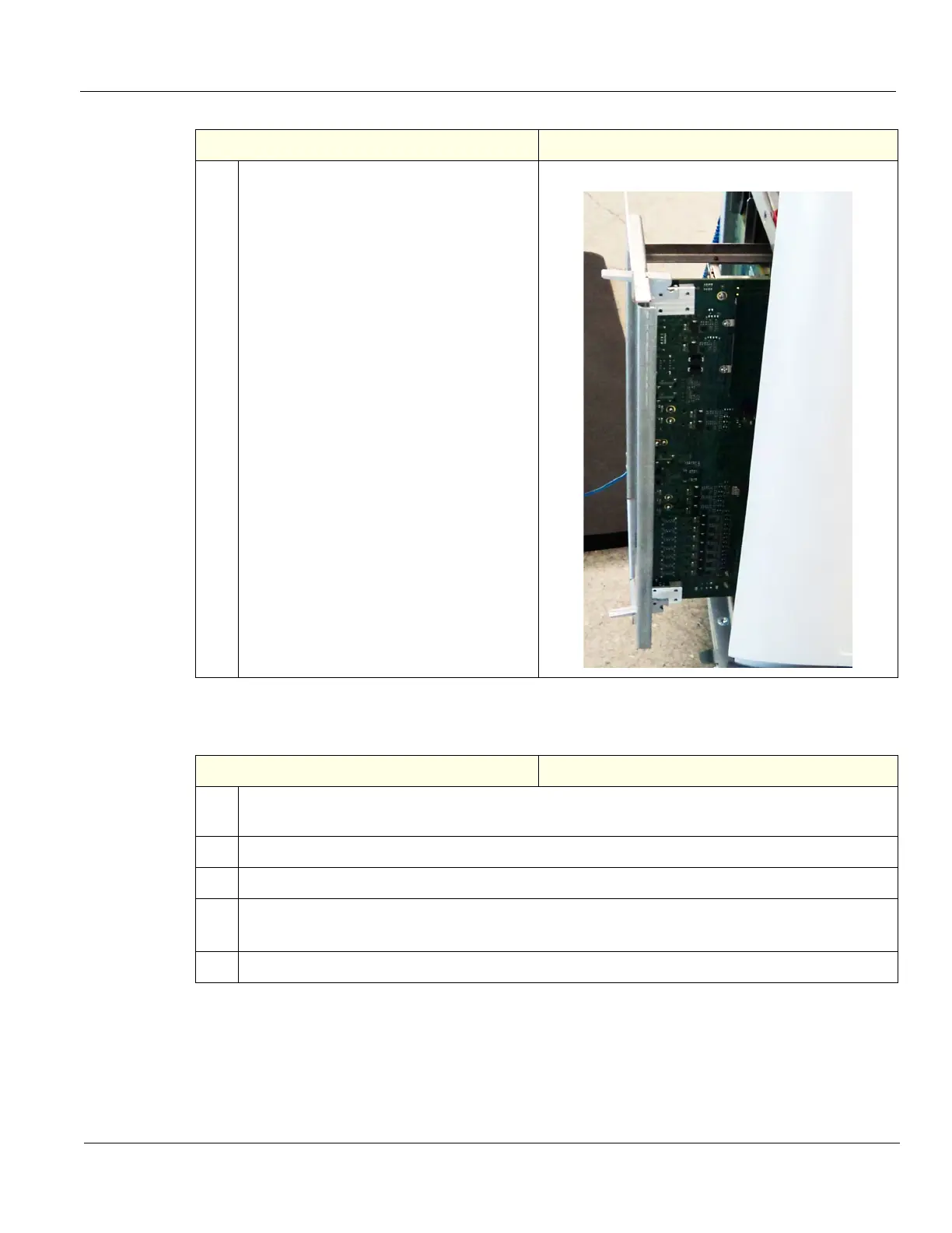
Continue to gently slide the ECB from the
Card Cage. Place on an ESD safe place,
with the GPU facing down.
A piece of ESD safe foam works well to
support the ECB flat.
ECB being removed
Table 8-303 ECB installation
Steps Corresponding Graphic
1. Carefully align the ECB with the rails and push in until it starts to seat in the Backplane
connectors and close the board ejector levers.
2. Re-install the two screws to secure the ECB to the Card Cage.
3. Re-connect all cabling to the ECB. See: "ECB cable connections" on page 8-276.
4. Install the Card Rack Cover and fasten it with the fixing screws.
Connect the Hi-Pass cable to the GRLY Board and re-install the cover, if present.
5. Re-install all Covers removed.
Table 8-302 ECB removal
Steps Corresponding Graphic