DIRECTION 5750007-1EN, REV. 1 LOGIQ E10 BASIC SERVICE MANUAL
8 - 308 Section 8-11 - Front End Acquisition / Card Cage parts replacement
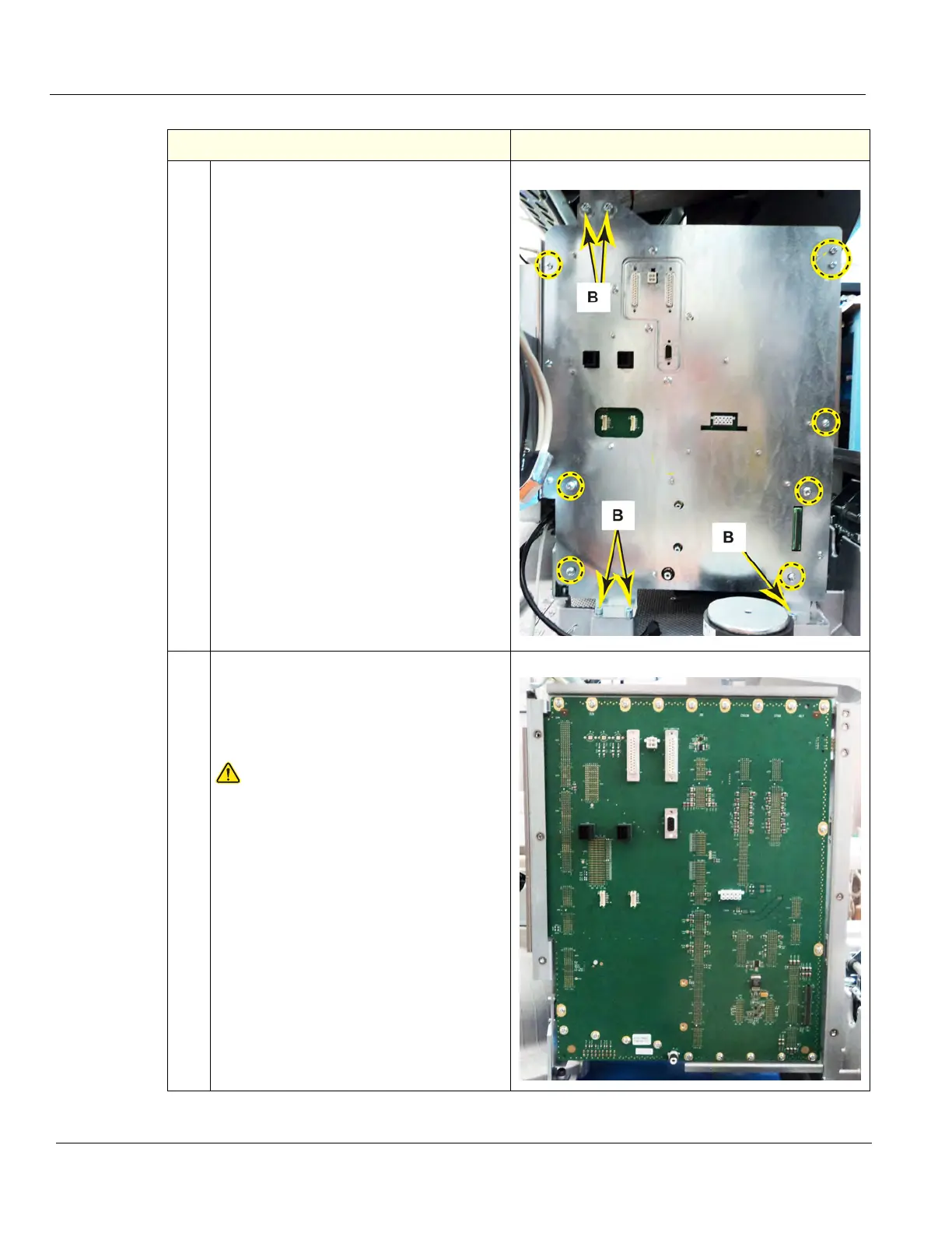
15.
Remove the five M6 screws (B) that secure
the Option Bracket to the Base Casting,
using a 5 mm hex wrench.
Starting at the bottom, remove the 7
Phillips screws that secure the Option
Bracket to the Card Cage, using a #2
Phillips screwdriver. BE SURE to support
the Bracket as it is being removed, it has
mass.
16.
Remove the 21 Phillips screws that ground
and secure the Backplane to the Card
Cage, using a #2 Phillips screwdriver. The
screws are around the perimeter of the
Backplane.
CAUTION
To avoid injury, handle the Backplane by
the edges. There are two guides to guide
the ECB onto the Backplane, which
protrude and are VERY SHARP.
Carefully remove the Backplane away from
the Card Cage by grasping the outer
edges, pulling out the right edge first, to
guide the connectors to the Main Power
Supply out of the Card Cage.
Table 8-329 Backplane removal
Steps Corresponding Graphic