DIRECTION 5750007-1EN, REV. 1 LOGIQ E10 BASIC SERVICE MANUAL
Chapter 8 Replacement Procedures 8 - 323
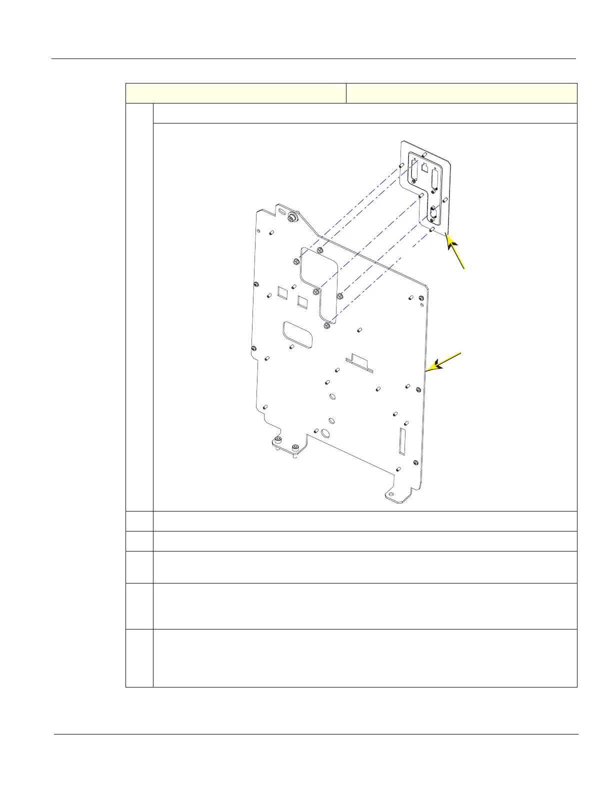
12.
The Connector Panel (C) is secured to the Option Bracket (D) with five flange nuts (E).
13.
Remove the Connector Panel flange nuts, using a 7 mm driver.
14.
Install the replacement Connector Panel to the Option Bracket.
15.
Transfer the four hex screwlocks and the two locking posts the Connector Panel.
Torque to 0.6 +/- 0.1 Nm (0.4 +/- 0.07 lbf-ft).
16. Re-install the Option Bracket. BE SURE to support the Bracket as it is being installed, it has
mass.
Re-install the five M6 screws that secure the Option Bracket to the Base Casting, loosely.
17. Starting at the top, re-install the 7 Phillips screws that secure the Option Bracket to the Card
Cage. Tighten alternately.
Torque the M6 screws to 3.7 +/- 0.6 Nm (2.7 +/- 0.44 lbf-ft), ONLY the M6 screws are torqued to
this value.
Table 8-334 Connector Panel replacement
Steps Corresponding Graphic
C
E
D