EasyManuals Logo

GE LOGIQ E10 Service Manual

GE LOGIQ E10
778 pages
To Next Page IconTo Next Page
To Previous Page IconTo Previous Page
Page #602 background imageLoading...
Page #602 background image
DIRECTION 5750007-1EN, REV. 1 LOGIQ E10 BASIC SERVICE MANUAL
8 - 356 Section 8-11 - Front End Acquisition / Card Cage parts replacement
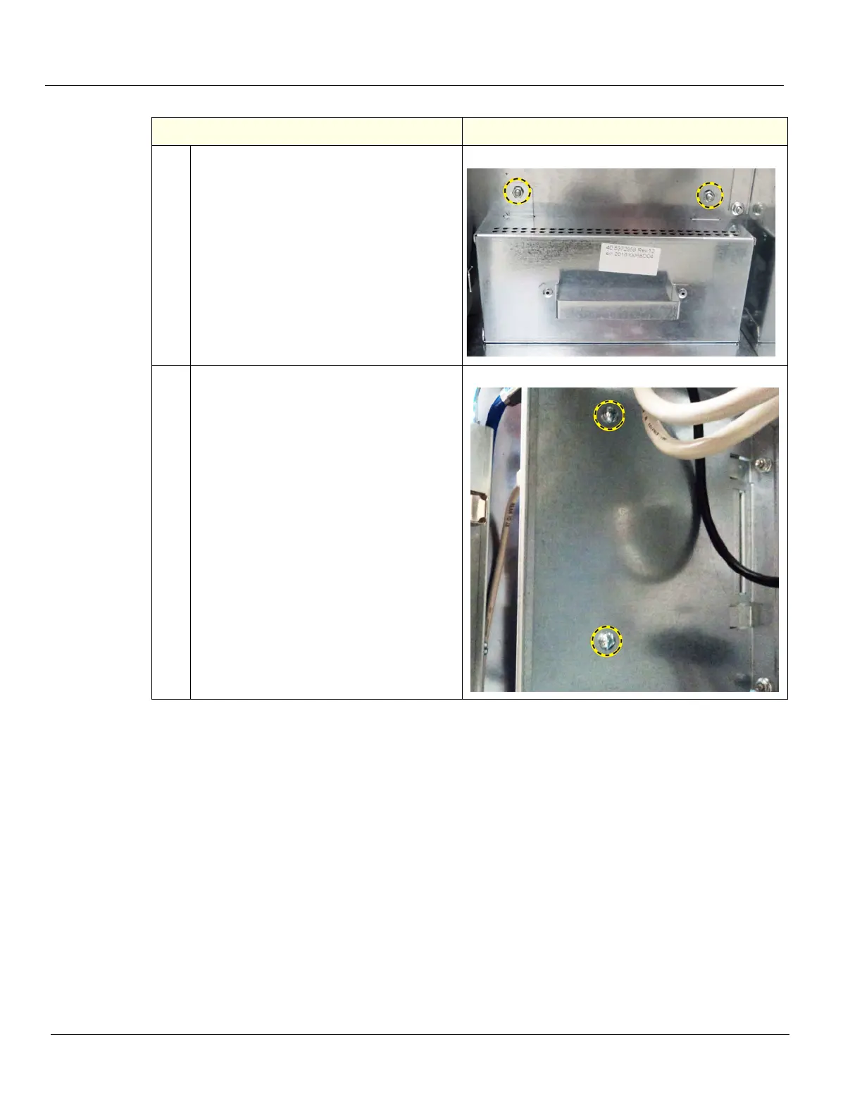
5.
Remove the two flange nuts securing the
4D Motor Controller Cover and slide the
Cover out.
It is not necessary to remove the 4D Board.
6.
Locate the two screws securing the Rear
I/O to the Option Box, above the Batteries.
Remove the screws using a #2 Phillips
screwdriver.
Table 8-368 Option Box removal
Steps Corresponding Graphic

Table of Contents

Other manuals for GE LOGIQ E10

Questions and Answers:

Question and Answer IconNeed help?

Do you have a question about the GE LOGIQ E10 and is the answer not in the manual?

GE LOGIQ E10 Specifications

General IconGeneral
TouchscreenYes
3D/4D ImagingYes
ApplicationsVascular, Cardiac, Musculoskeletal, OB/GYN
Image StorageUSB, Network
ConnectivityDICOM, Ethernet, Wireless

Related product manuals