GE COMPANY
DIRECTION 5472001-1EN, REVISION 6OPTIMA CT680 SERIES AND OPTIMA CT670 INSTALLATION MANUAL
Page 48 Section 7.0 - Gantry Bearing Gap Inspection
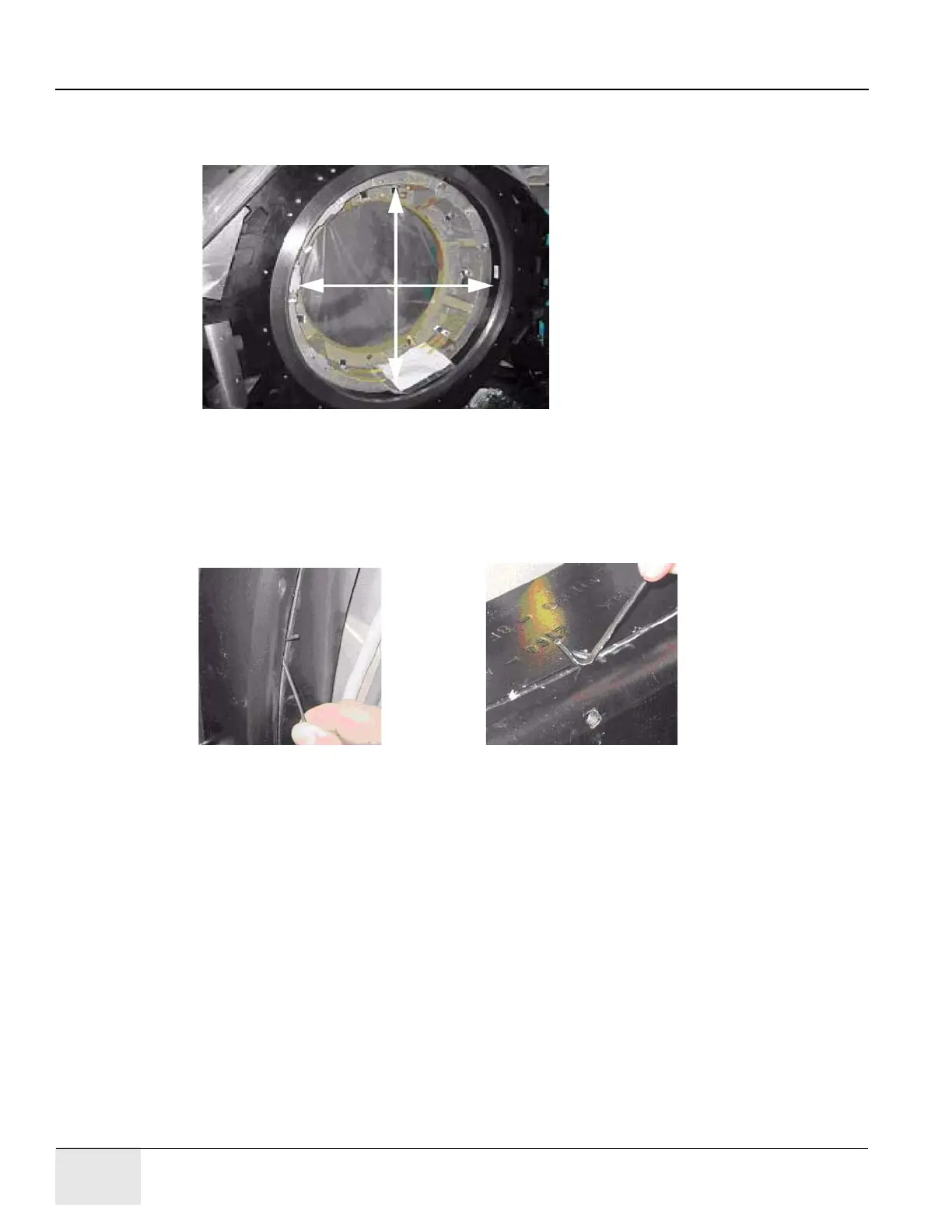
4.) Use a 2.5 mm hex wrench as a tool to measure the gap at the positions shown in Figure 1-16.
The location of gantry components does not matter. Measure four (4) locations 90 degrees
apart from each other.
Figure 1-16 Inspection Locations
5.) If the 2.5 mm easily fits without effort in the gap, the gap is out of spec. Figure 1-17 shows a
gap that is too large in the left picture. Figure 1-17 shows a gap that is good in the right picture.
Notice that the hex wrench does not fit in the gap in Figure 1-17 (left picture), but does in
Figure 1-17 (right picture).
Note: Do not use force when putting the wrench in the gap. Either it slips in or it doesn’t.
Figure 1-17 Gap too large (left) Gap is good (right)
7.5 Finalization
7.5.1 Mechanical Installers
If the Bearing Gap Inspection passes, complete the sign-off on the GE Form e4879, Installation
Data verification form, that this inspection was completed.
If the Bearing Gap Inspection fails, contact your site FE.
7.5.2 FE Service Action, if Required
If the Bearing Gap Inspection fails, the mechanical installer notifies the site FE that the inspection
failed.
The site FE should:
1.) Open a bearing inspection dispatch.
2.) Follow the inspection procedure described in this section.
3.) Record the bearing inspection results.

 Loading...


