GE COMPANY
DIRECTION 5472001-1EN, REVISION 6OPTIMA CT680 SERIES AND OPTIMA CT670 INSTALLATION MANUAL
Chapter 2 - Power, Ground & Interconnect Cables Page 123
2 – Install Power
Section 6.0 Table Connections (GT1700V)
Pull and connect the cables as described in Table 2-12. The table cables are bundled with the
gantry frame. Cut the cable ties to release bundles of cables.
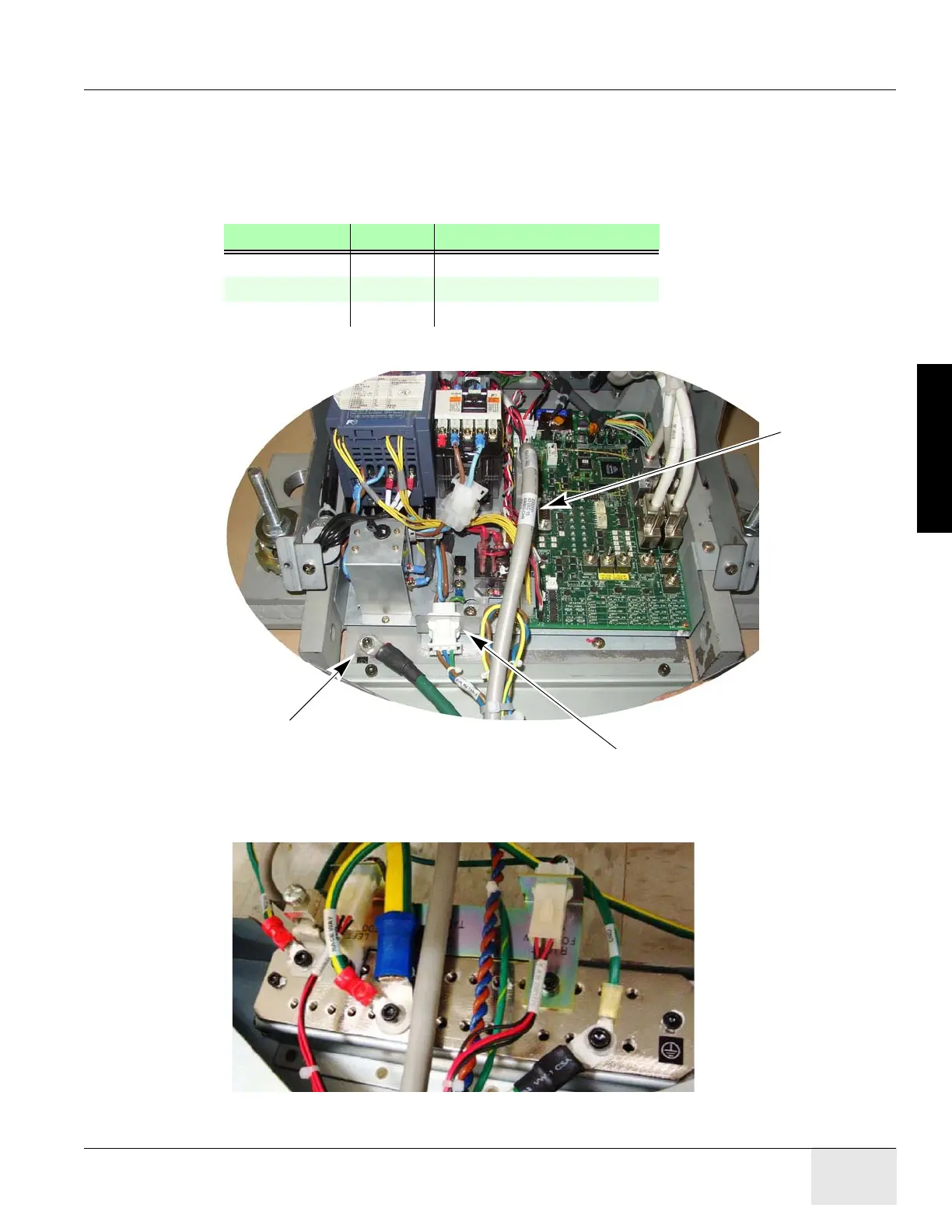
Note: The footswitch connector and wiring harness may be run and secured to the ground bar assembly.
Figure 2-26 Table Connections
Note: You need to add the table ground cable and the footswitch adapter plate to ground bar, as shown.
Figure 2-27 Finished Ground Bar Connections
TABLE FROM CABLE DESCRIPTION
J1 table power Gantry 120 VAC
J9 table control Gantry Signal Cable
Table ground Gantry Table ground
Table 2-12 Table Cable Connections

 Loading...


