GE COMPANY
DIRECTION 5472001-1EN, REVISION 6OPTIMA CT680 SERIES AND OPTIMA CT670 INSTALLATION MANUAL
Chapter 1 - Position Subsystems Page 59
1 – Pos. Subsystems
3.) Lower the table to the floor using the dollies, making sure to maintain the 673mm (26.5 in.)
distance.
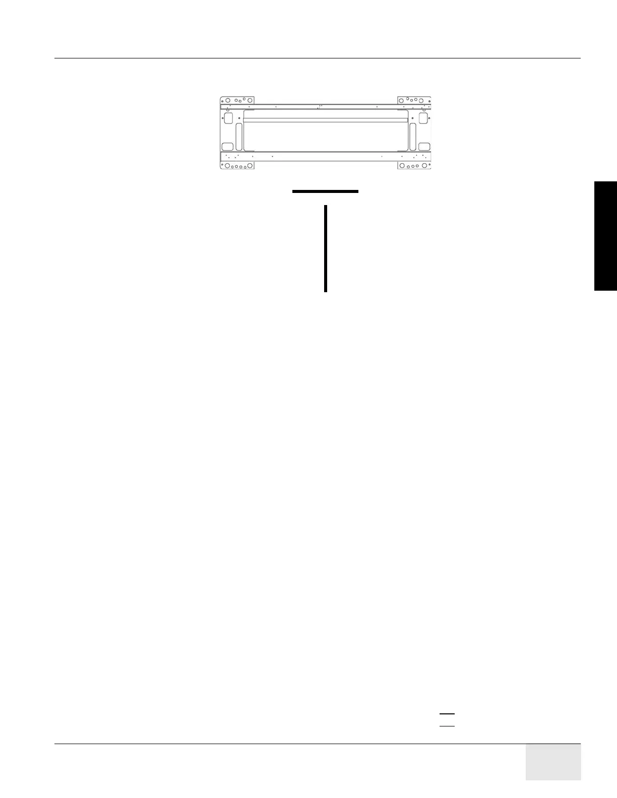
Figure 1-35 Two Reference Lines
9.3.6 Level and Center the Table to the Gantry
9.3.6.1 Conditions
• Before you start, turn on the laser and check that the beam is still on the mark placed on the
wall. If not, reset the laser.
• If the mark is not present, use a measuring tape and place a 102 mm (4 in.) piece of masking
tape on the cradle at the 1000 mm and on the laser line.
• Table base to cradle alignment location is 1005 mm from the center of cradle to the floor.
9.3.6.2 Specifications
• Table cradle must be level in all directions (centered within the lines on a Johnson Professional
level).
• All table adjusters should be preset to 15.5 mm (5/8 in.) down from the table base to make
adjustment easier. Based on floor levelness and your experience, a different preset height may
work better. One thread must be showing above all locking rings when leveled.
• Table cannot be higher than 1005 mm from floor to cradle.
9.3.6.3 Procedure
NOTICE Avoid leaning on the cradle during this procedure.
DO NOT pin the gantry during this alignment process.
This procedure as described is for systems mounted on 4 in. (102 mm) concrete floors only!
Note: If the floor covering was not properly removed with the glue removed or the levelers were not
centered over the floor cutouts, the leveler may become trapped against the edge of the floor
covering, causing the table to become unleveled. If this happens, move the table and enlarge the 4
in. (102 mm) floor cutout for the table. Glue removal is important and aids in moving the table to its
final location.
1.) Have the table side panels removed and have a ratchet, 1-1/8" socket, and a 2-foot level ready
to use.
2.) Turn on the laser’s "I" beam (vertical beams) by pressing the ON
button 2 times.
Reference line for table Z-distance
Reference line for table perpendicularity

 Loading...


