GE COMPANY
DIRECTION 5472001-1EN, REVISION 6OPTIMA CT680 SERIES AND OPTIMA CT670 INSTALLATION MANUAL
Page 162 Section 6.0 - Electrical Power On & Ground Checks
4.) Use a 0-750 AC voltmeter of 3/4% accuracy to measure the line-to-line voltages at L1, L2, &
L3.
- Verify the highest line-to-line voltage does not exceed 1.02 times the lowest voltage.
- Example: If the lowest voltage equals 474, the highest voltage should not exceed 474 x
1.02 = 483.5 volts.
WARNING THIS PROCEDURE MEASURES POTENTIALLY HAZARDOUS VOLTAGES. USE AND
FOLLOW LOCKOUT/TAGOUT PROCEDURES.
Record system voltages here:
Phase A: _______ Phase B: _______ Phase C: _________
6.7 System Power-Up
CAUTION Verify all personnel have cleared the system before you turn on wall power.
1.) Turn ON the A1 breaker panel.
Note: Do not stand in front of the main disconnect to turn on power.
2.) Turn ON all system power switches and breakers (PDU, gantry, table, console).
- All PDU breakers
- Make sure that the on/off button (on the front PDU panel) is ON for console power.
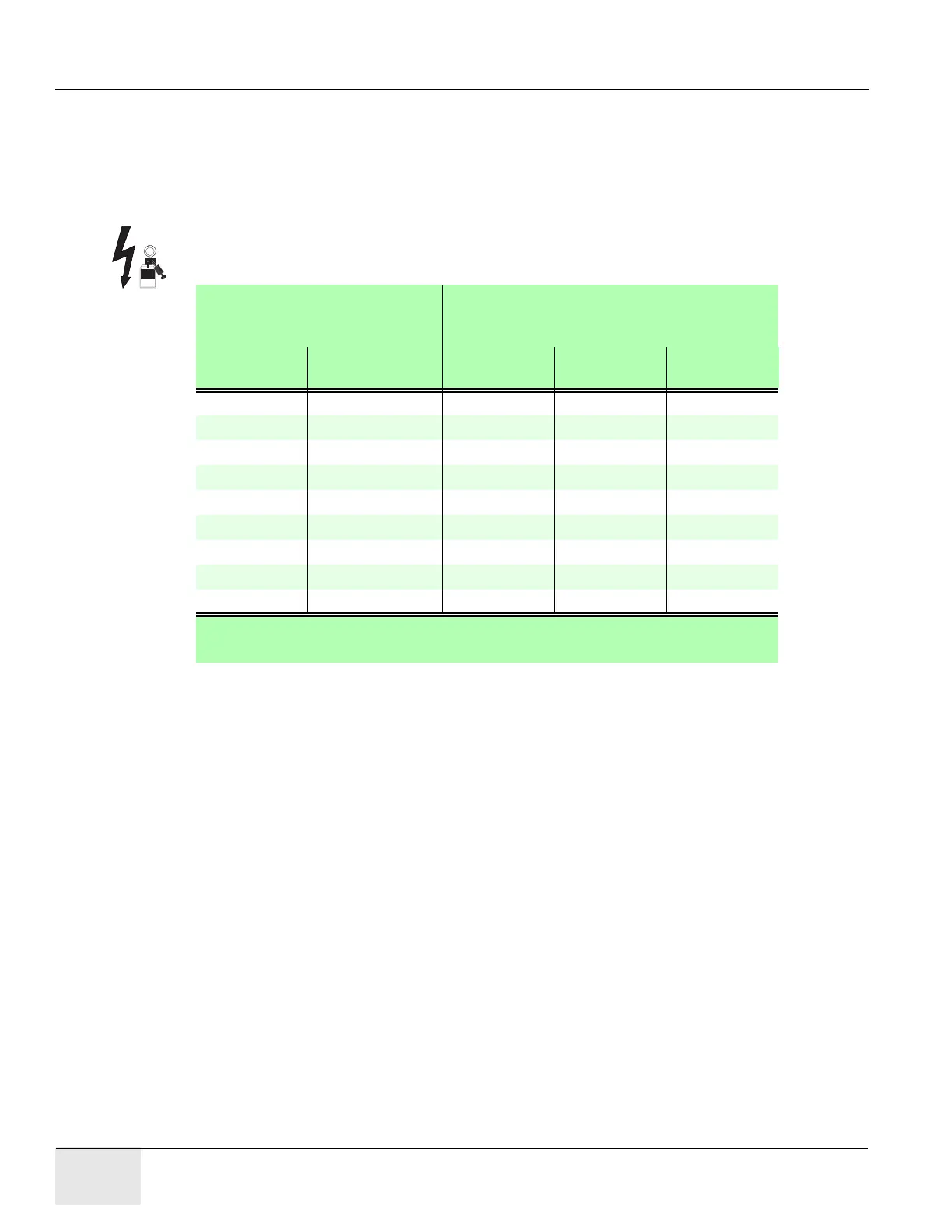
No Load
Line to Line Voltages
Tap Connections
(All 3 phases must have same the
configuration)
Nominal Maximum Range
(10%)
Phase A
Connection
Phase B
Connection
Phase C
Connection
480V* 432 to 528* 3-4* 3-4* 3-4*
460V 414 to 506 3-5 3-5 3-5
440V 396 to 484 3-6 3-6 3-6
420V 378 to 462 2-4 2-4 2-4
400V 360 to 440 2-5 2-5 2-5
380V 342 to 418 2-6 2-6 2-6
240V** 216 to 264** 1-4** 1-4** 1-4**
220V** 198 to 242** 1-5** 1-5** 1-5**
200V** 180 to 220** 1-6** 1-6** 1-6**
* Factory Default
** 2326492-3 PDU only
Table 4-1 PDU Line Tap Connections
 Loading...


