GE COMPANY
DIRECTION 5472001-1EN, REVISION 6OPTIMA CT680 SERIES AND OPTIMA CT670 INSTALLATION MANUAL
Chapter 4 - System Covers: Installation & Alignment Page 163
4 - Continuity Checks
- Gantry power pan breaker
- All gantry service switches
- Table base power
- Console power (Check internal breaker.)
Note: (16BW45.x or later)
User Logon screen will appear during system start up.
SUB-SYSTEM POWER-UP
1.) Turn ON switch S3 in the table (120VAC 24-hour power).
2.) Turn the gantry 120 - 208VAC
to ON. (Light should turn on.)
3.) Turn AXIAL DRIVE ENABLE
ON. (Light should turn on.)
4.) Turn HV DC ENABLE
ON. (Light should turn on.)
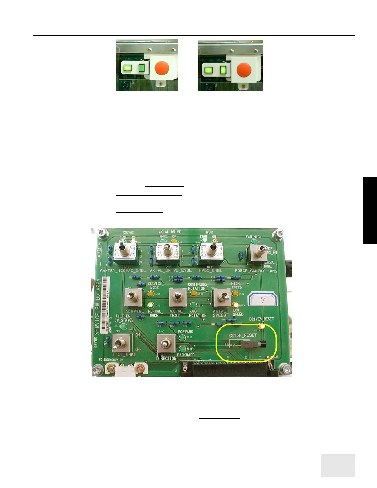
5.) Push the Service Switch Panel reset button. (See Figure 4-24)
Figure 4-24 Service Switch Panel
AXIAL ENABLE SWITCH TEST
1.) Unplug all top cover fan plugs.
2.) Turn OFF axial drive enable switch AXIAL_DRIVE
on the Service Switch Panel.
Note: For the initial condition, do NOT leave the tube at the 2:30 position.
3.) Clear the gantry area for rotation.
PDU Power Switch OnPDU Power Switch Off

 Loading...


