GE COMPANY
DIRECTION 5472001-1EN, REVISION 6OPTIMA CT680 SERIES AND OPTIMA CT670 INSTALLATION MANUAL
Page 126 Section 8.0 - PDU Cable Connections & Configuration
8.1.1 Panel - 380 - 480VAC Mains “TS1” Input Power Connection
1.) Remove the TS3 panel front cover.
2.) Strip the wires to fit securely on the power block.
3.) Observe incoming phases (L1, L2 and L3) and insert bare leads into power block.
4.) Insert “vault” ground into PDU “vault” ground lug.
5.) Tighten all fasteners securely and replace the TS3 front panel.
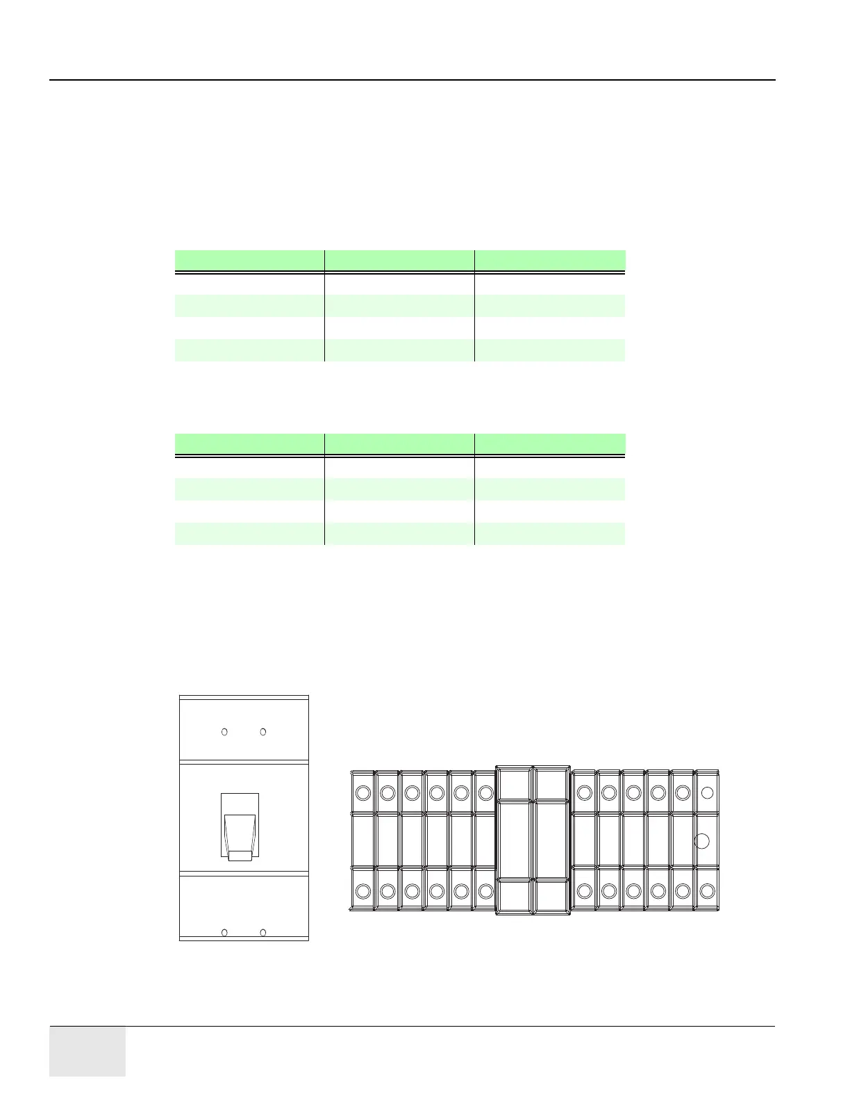
8.1.2 Panel - Circuit Breakers
Place the circuit breakers in the “off/down” position during installation, even with Mains incoming
power tagged and locked out. After you have completed work on the PDU, you may return the circuit
breakers to the “ON” positions.
Figure 2-30 Circuit Breaker Panel
Wire Size AWG Driver Bolt/Hex
#18 - 16 1.67 ft-lb (2.3 N-m) 6.25 (8.5 N-m)
#14 - 8 1.67 ft-lb (2.3 N-m) 6.25 (8.5 N-m)
#6 - 4 3.0 ft-lb (4.1 N-m) 12.5 (17 N-m)
#0 - 2/0 29 ft-lb (39.3 N-m)
Table 2-14 Power Wire Torque Values
Wire Size AWG Driver Bolt/Hex
#14 - 8 1.67 ft-lb (2.3 N-m) 6.25 (8.5 N-m)
#6 - 4 3.0 ft-lb (4.1 N-m) 12.5 (17 N-m)
#3 - 1 21 ft-lb (28.5 N-m)
#0 - 2/0 29 ft-lb (39.3 N-m)
Table 2-15 Ground Buss Bar Torque Values
CB1
VMR1
VMR2
CB4
CB5
CB2
CB3
CB6
CB7
CB9
CB10

 Loading...


