GE COMPANY
DIRECTION 5472001-1EN, REVISION 6OPTIMA CT680 SERIES AND OPTIMA CT670 INSTALLATION MANUAL
Chapter 4 - System Covers: Installation & Alignment Page 159
4 - Continuity Checks
6.1 Introduction and Flowchart
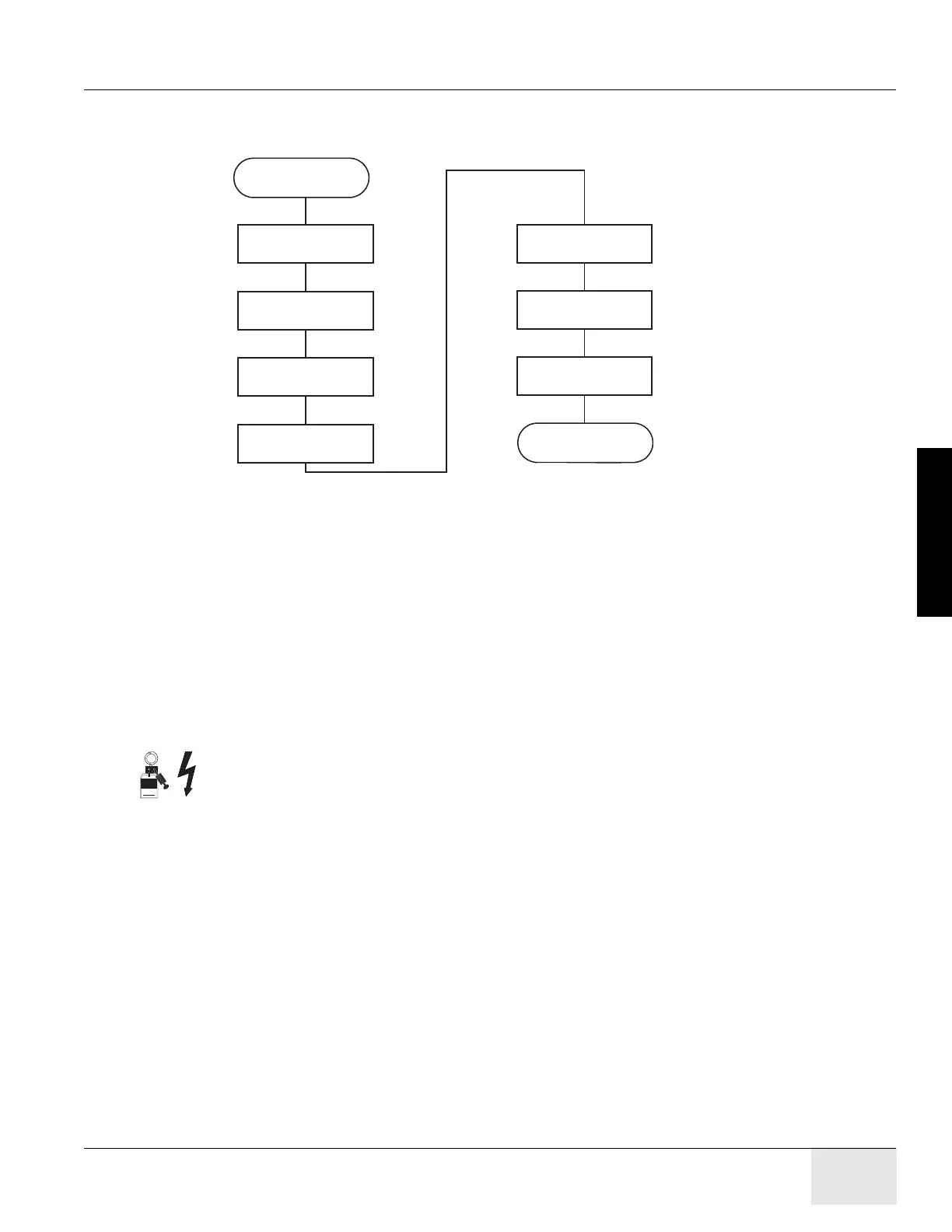
6.2 Electrical Power On & Ground Checks Process Overview
6.3 Required Tools
• Multimeter with a rating of at least 1000 volts
• Multimeter leads with a rating of at least 1000 volts
6.4 Initial PDU Configuration
WARNING THIS PROCEDURE MEASURES POTENTIALLY HAZARDOUS VOLTAGES. USE AND
FOLLOW LOCKOUT/TAGOUT PROCEDURES.
6.4.1 Circuit Breakers
Set all PDU, gantry, console, and table circuit breakers to OFF.
6.4.2 Relay Board
1.) Set SW 2 to the Auto-Off position.
2.) When the system is powered, three lamps should be "ON". (Refer to Figure 4-22.)
Required
Tools
Start
Line Transformer
Settings
System
Power-Up
Emergency Stop
Check
End
Initial PDU
Configuration
Power
Switches
Suite Emergency
Off Checks

 Loading...


