GE COMPANY
DIRECTION 5472001-1EN, REVISION 6OPTIMA CT680 SERIES AND OPTIMA CT670 INSTALLATION MANUAL
Chapter 4 - System Covers: Installation & Alignment Page 153
4 - Continuity Checks
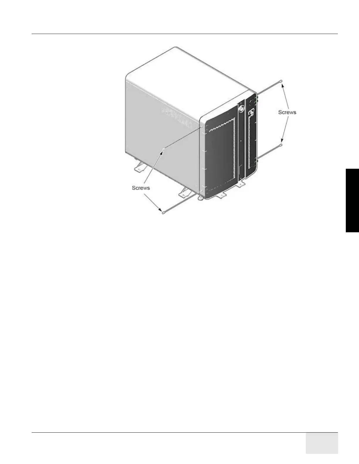
3.) Install four screws (two screws on each side).
Figure 4-16 Install Front Cover Screws
Section 3.0 Table Cover Installation (GT1700V)
3.1 Side Covers
1.) Remove screws (2) on tape switch.
2.) Remove back under-side covers (2) plus black screws.
3.) Undo the 2 red/black connectors.
4.) Remove all six (6) 4mm hex-head screws.
3.2 Install Panels
3.2.1 Top Panel #1
1.) Install two (2) 4mm hex-head screws. Leave them loose until the bottom screws are installed.
2.) Install 6nd wire using one (1) 4mm hex-head screw.
3.2.2 Bottom Panel #1
1.) Install white washer between grey base and panel. Insert Phillips screw into the bushing.
2.) Tighten top screws. (Torque 8 lb-in)
Note: Second panel over laps the first panel

 Loading...


