GE COMPANY
DIRECTION 5472001-1EN, REVISION 6OPTIMA CT680 SERIES AND OPTIMA CT670 INSTALLATION MANUAL
Appendix A – Gantry Cover Removal and Dolly Setup Page 183
A - Covers
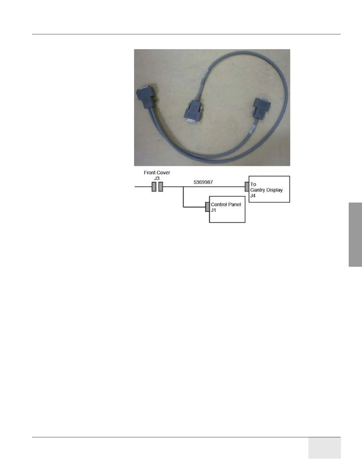
end of the connectors to display and control panel.
Figure A-27 FRT CVR J3 Cable
1.3.5 Bore Cover Removal
1.) Remove gantry side covers, top covers and Mylar window. Refer to each cover’s removal
procedure.
2.) Remove gantry rear and move away from the gantry. Refer to Gantry Rear Cover Removal
procedure.
3.) Disconnect the Breath Navigator I/F cable and MIC REAR T-SW I/F cable from the top of the
bore cover.

 Loading...


