GE COMPANY
DIRECTION 5472001-1EN, REVISION 6OPTIMA CT680 SERIES AND OPTIMA CT670 INSTALLATION MANUAL
Page 182 Section 1.0 - Gantry Cover Removal
c.) Align the ball studs with their associated receivers and snap into place.
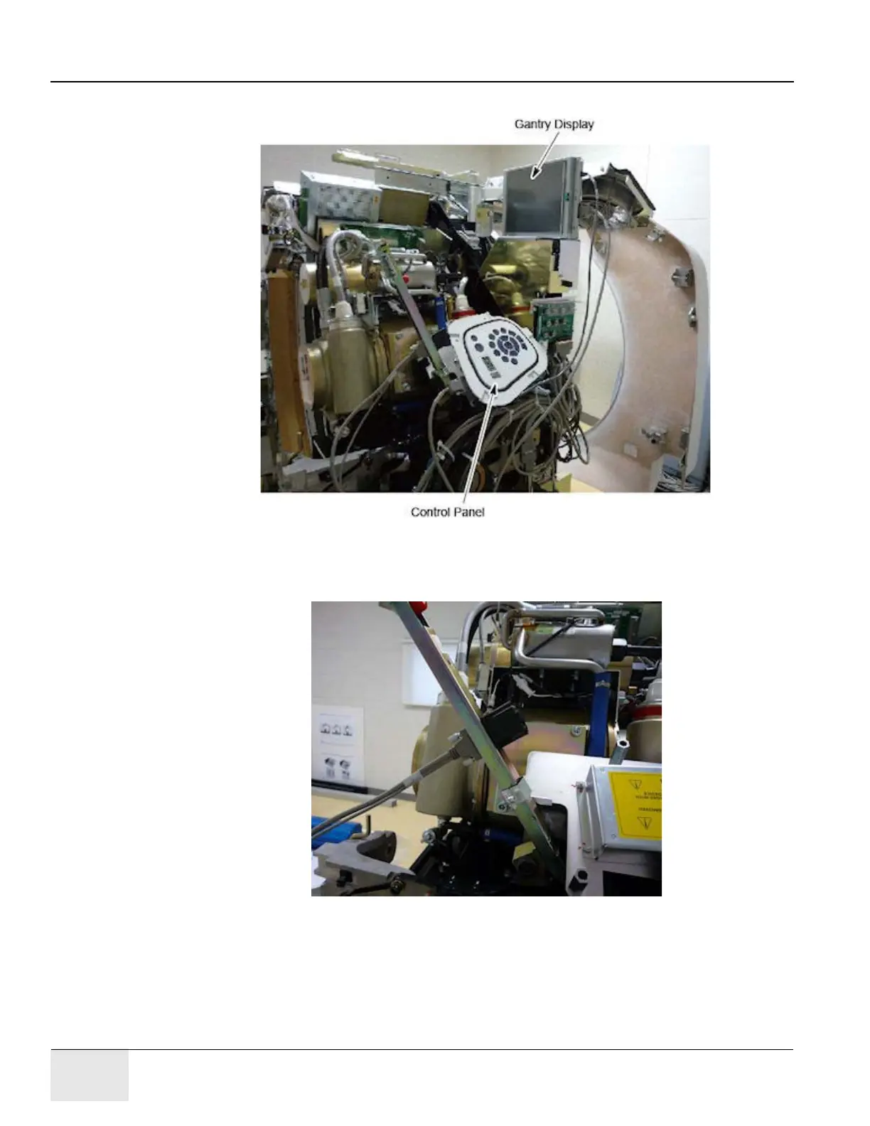
Figure A-25 Control Panel Service Position
d.) Connect FCVR BKHD J1 cable to terminator located on the cantrell arm. See Figure A-
26.
Figure A-26 Gantry Service Mode Cable Terminator
e.) Connect the FRT CVR J3 cable to the extension cable 5369987 and connect the other

 Loading...


