GE COMPANY
DIRECTION 5472001-1EN, REVISION 6OPTIMA CT680 SERIES AND OPTIMA CT670 INSTALLATION MANUAL
Chapter 2 - Power, Ground & Interconnect Cables Page 127
2 – Install Power
8.1.3 HVDC Connection
Note: Refer to Table 2-3, System Interconnect Cables on page 100.
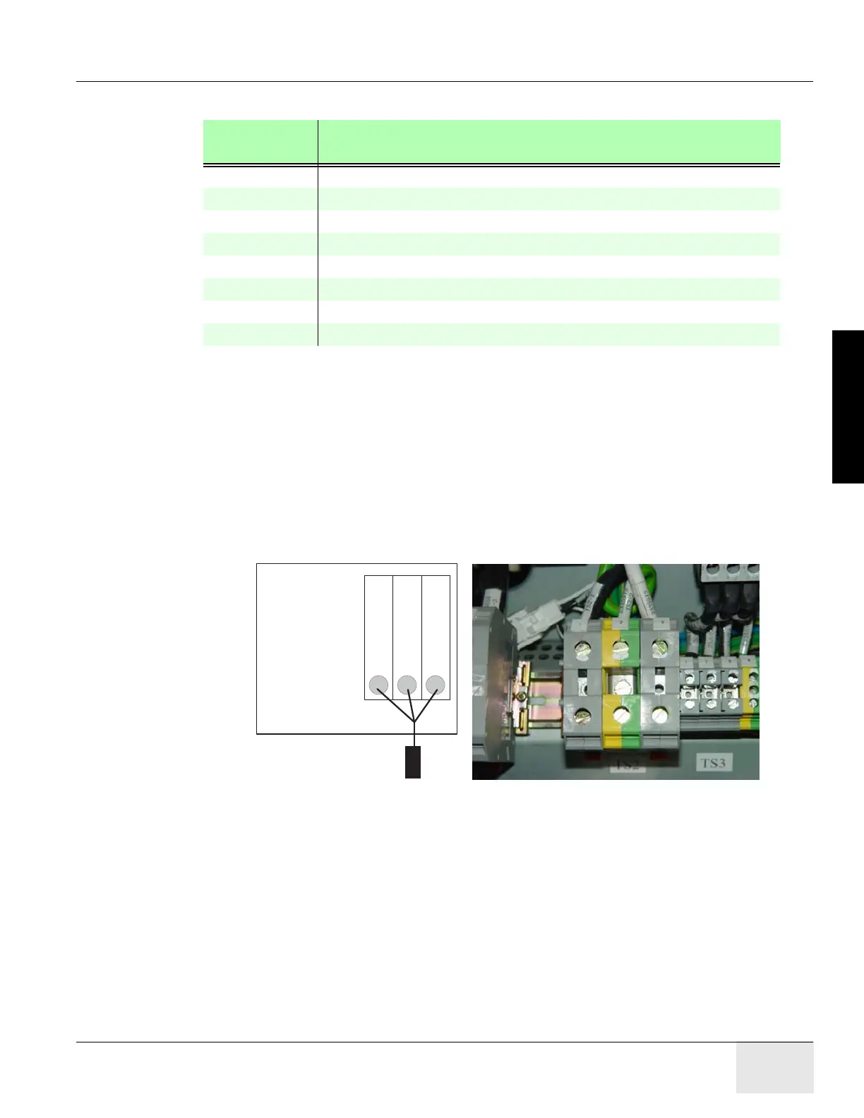
Connect the internally shielded HVDC cable to TS2 on the standing panel. See Figure 2-29 for the
location of the connector and Figure 2-31 for details. Observe polarities and grounds. Do not cut or
shorten cables unless you have all of the appropriate tools and crimper to re-terminate. If short
cables are needed, have the PMI order the short cable set.
WARNING Excess cable length cannot be stored under or behind the PDU. If cables are to be stored in the
cable tray, do not overfill. Consult the local electrician to determine the maximum fill rate for your
area.
Figure 2-31 HVDC Connection
Check box when complete.
CIRCUIT
BREAKER
DESCRIPTION
CB2 Circuit Protection (Axial Drive)
CB3 Full Winding Protection
CB4 CT Gantry Service Outlets
CB5 CT Gantry rotating loads
CB6 Table & CT Gantry Stationary Loads
CB7 Operator Console Load
CB9 VMR1, Control P.S Load
CB10 VMR2
Table 2-16 Panel Circuit Breaker Descriptions
Install Shield Clamp tightly
around exposed Cable Shield
at lower left of PDU.
TS2-1 (Red)
TS2-3 (Black)
Ground
+
-
(Shield)
Standing Panel - HVDC SUPPLY
OUTPUT CONNETCTIONS

 Loading...


