GE COMPANY
DIRECTION 5472001-1EN, REVISION 6OPTIMA CT680 SERIES AND OPTIMA CT670 INSTALLATION MANUAL
Chapter 1 - Position Subsystems Page 85
1 – Pos. Subsystems
Section 13.0 Install Table Footswitch Assembly (GT1700V)
13.1 Time and Personnel
13.2 Tools and Test Equipment
• Standard Install Tool Kit
13.3 Procedure
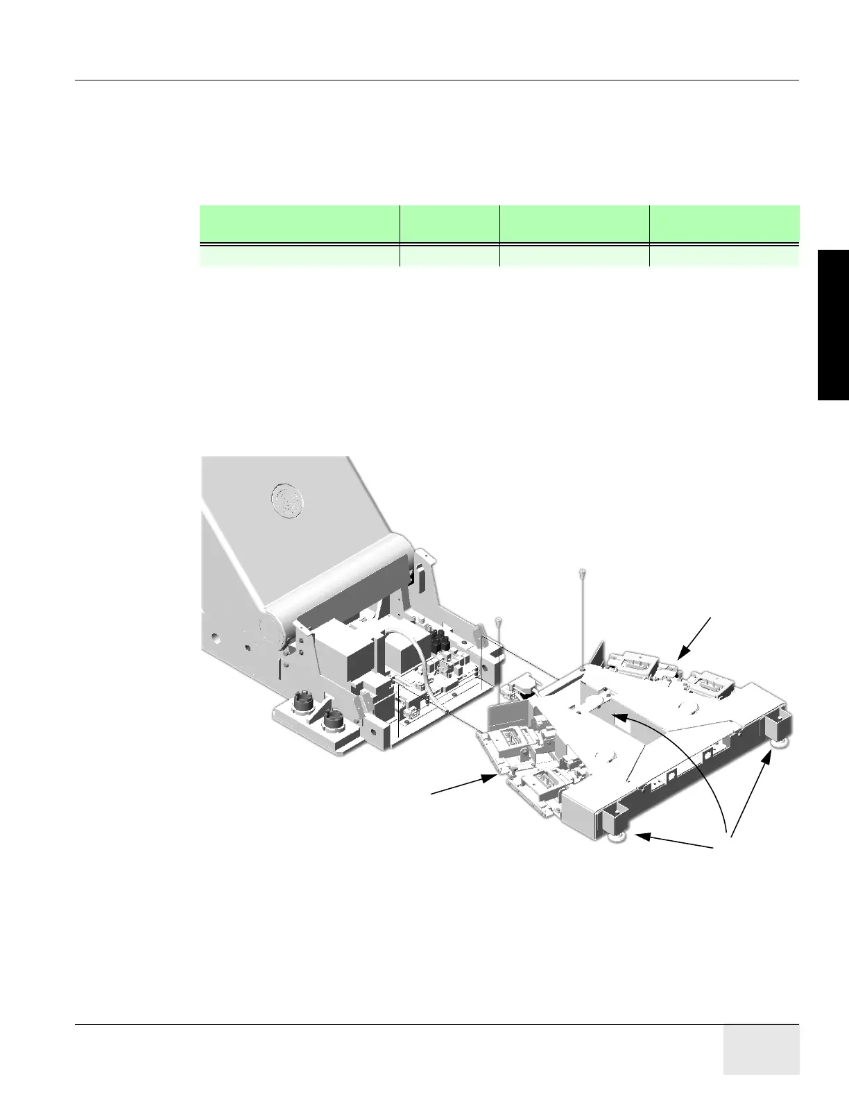
After table positioning is completed and the anchors are installed, install the footswitch assembly
as shown in Figure 1-66.
Figure 1-66 Footswitch Assembly Installation
1.) Pop off foot pedal screw cover tabs.
2.) Remove foot switch covers.
3.) Remove 3 Phillips screws that secure the assembly cover.
Required Persons Preliminary
Reqs
Procedure Finalization
1 (FE or mechanical supplier) 1.0 hour labor on-site
Footswitch
Support
Screws
Footswitch
Support
Screws
Footswitch
Level
Adjusters

 Loading...


