GE COMPANY
DIRECTION 5472001-1EN, REVISION 6OPTIMA CT680 SERIES AND OPTIMA CT670 INSTALLATION MANUAL
Page 86 Section 13.0 - Install Table Footswitch Assembly (GT1700V)
4.) Remove the footswitch assembly cover.
5.) Using two (2) M6 bolts, attach the footswitch assembly to the table base.
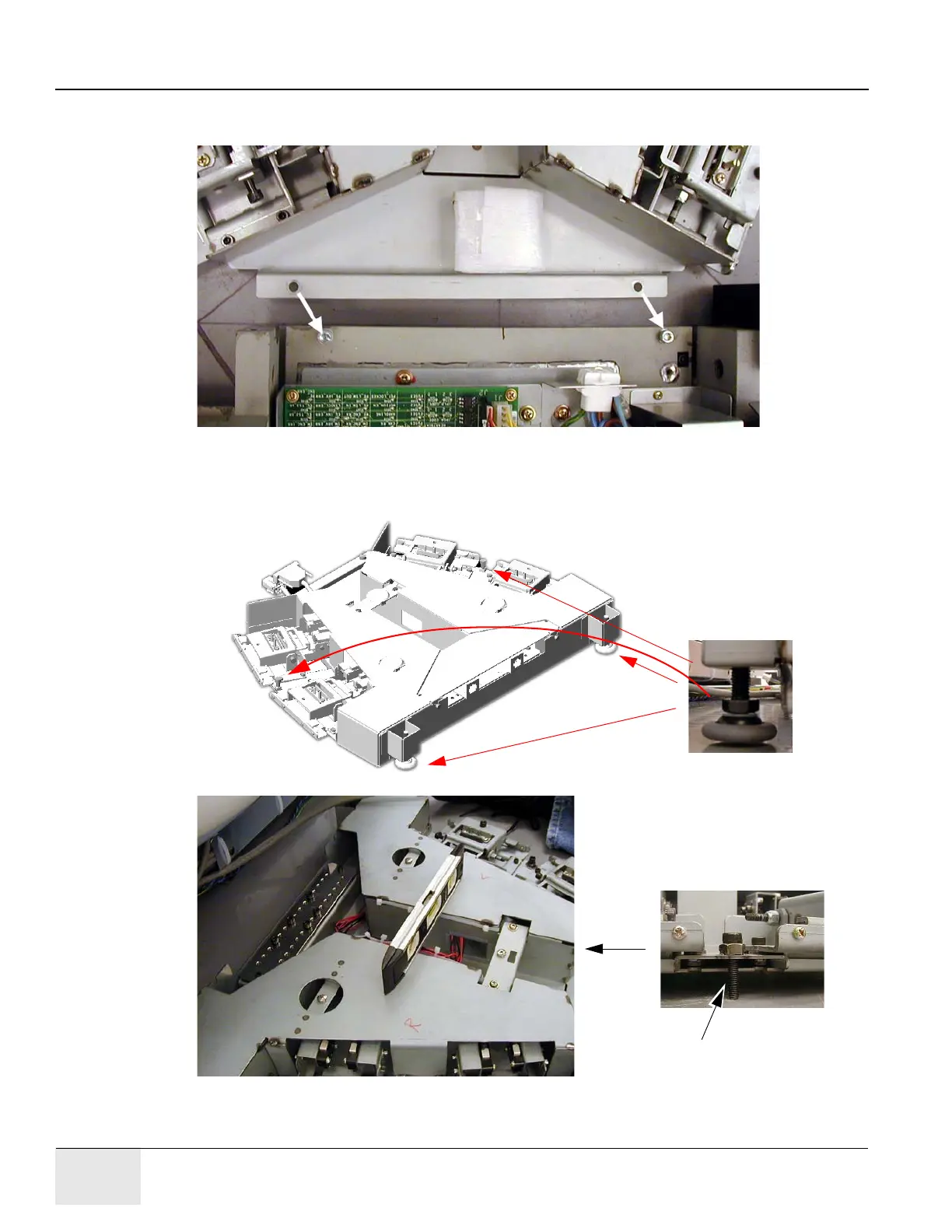
Figure 1-67 Attach Footswitch
6.) Level the footswitch assembly using the three (3) level adjusters. Two are on the gantry side
and one is in the middle. Use a 9 in. level to check the levelness in all directions.
Figure 1-68 Level Footswitch

 Loading...


