GE COMPANY
DIRECTION 5472001-1EN, REVISION 6OPTIMA CT680 SERIES AND OPTIMA CT670 INSTALLATION MANUAL
Chapter 1 - Position Subsystems Page 87
1 – Pos. Subsystems
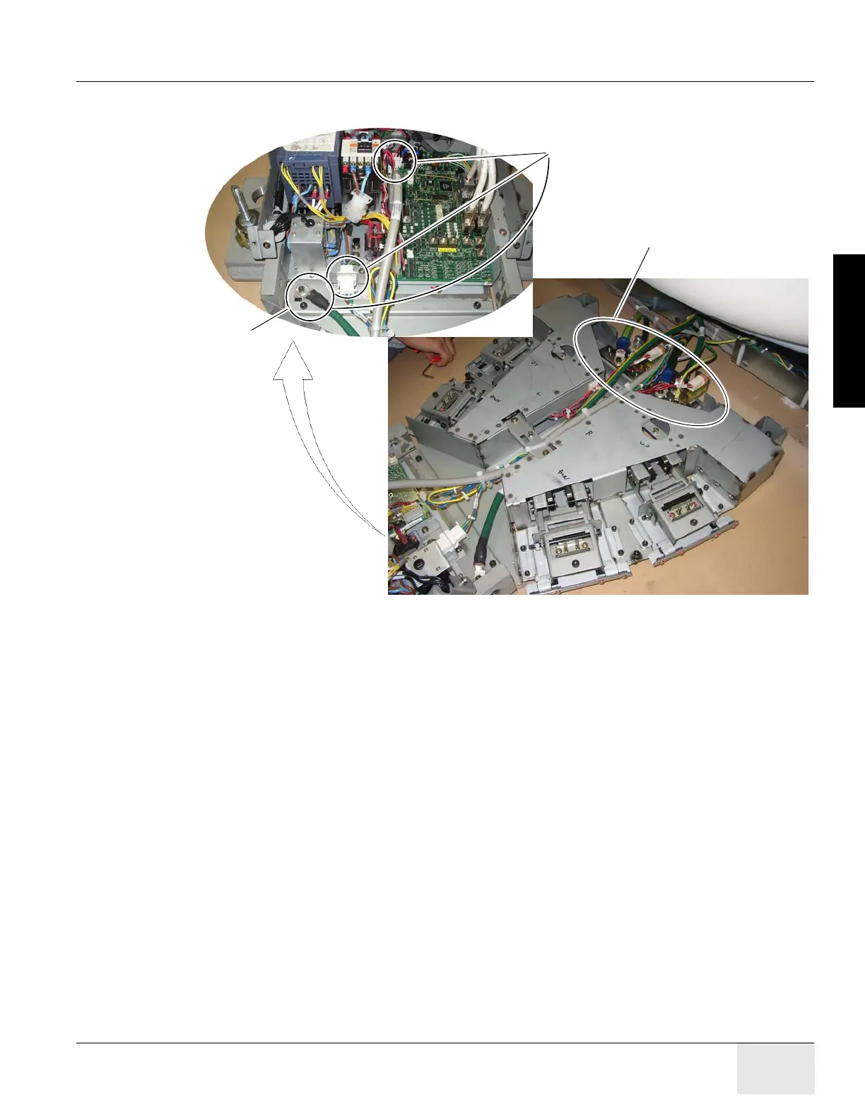
7.) Cut the tie-wraps from around the cables in the gantry base and route the power cables from
the gantry as shown in Figure 1-69.
Figure 1-69 Footswitch Assembly Cable Wiring
8.) Connect the ground bus connector plate.
Note: Additional M6 Hex-screws may be required to connect grounds.
Connect cable connector to J9,
GND cable to table frame
and power to power connector.
Ground Bus
M4 cap
screws

 Loading...


