GE COMPANY
DIRECTION 5472001-1EN, REVISION 6OPTIMA CT680 SERIES AND OPTIMA CT670 INSTALLATION MANUAL
Page 88 Section 13.0 - Install Table Footswitch Assembly (GT1700V)
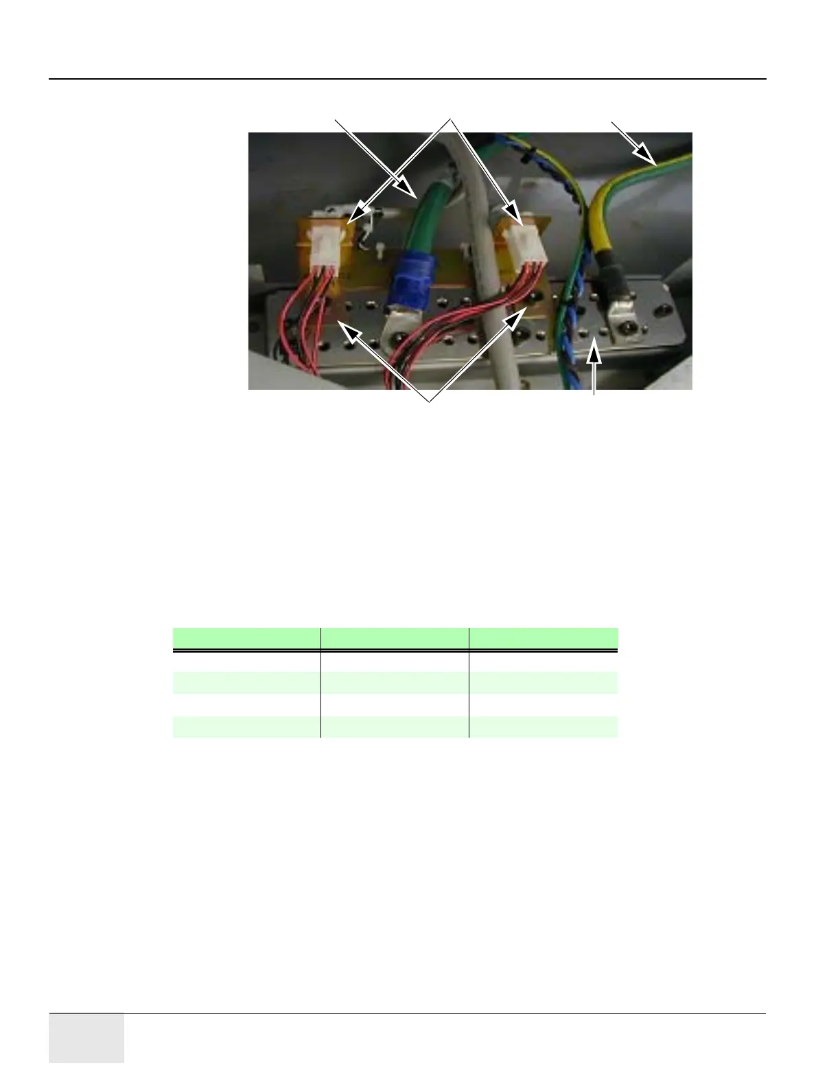
Figure 1-70 Footswitch Ground/Bus Bar
9.) Install the footswitch pedal bracket onto the installed ground bus bar.
Connect the ground wires (not all shown in Figure 1-70) to the installed ground bus:
Table#2
Gantry#1/0 and #10 and 2-#8 (Optional)
Console#2
PDU#1/0
10.) Torque per Table 1-7.
11.) Install all footswitch covers after work is completed. See Section 1.8 Install Gantry Base
Covers, on page 148.
Wire Size AWG Driver Bolt/Hex
#14 - 8 1.67 ft-lb (2.3 N-m) 6.25 (8.5 N-m)
#6 - 4 3.0 ft-lb (4.1 N-m) 12.5 (17 N-m)
#3 - 1 21 ft-lb (28.5 N-m)
#0 - 2/0 29 ft-lb (39.3 N-m)
Table 1-7 Ground Buss Bar Torque Values
Ground Wire
Footswitch
Connectors
Ground Wire
Ground Bus Connector Plate
Ground Bar

 Loading...


