GE COMPANY
DIRECTION 5472001-1EN, REVISION 6OPTIMA CT680 SERIES AND OPTIMA CT670 INSTALLATION MANUAL
Page 54 Section 9.0 - Table Installation (GT1700V)
Section 9.0 Table Installation (GT1700V)
Note: For Lite Table Installation, refer to Section 10.0.
9.1 Time and Personnel
9.2 Tools and Test Equipment
• Standard Install Tool Kit
• 3/4", 1-1/4", 1-1/2" and 1-5/8" sockets
• 8mm, 10mm, and 14mm hex socket bits
• Laser Alignment kit
• Johnson Professional 6" level
• Johnson Professional 4’ level
• Johnson Professional 2’ level
9.3 Procedures
9.3.1 Draw Table Reference Lines
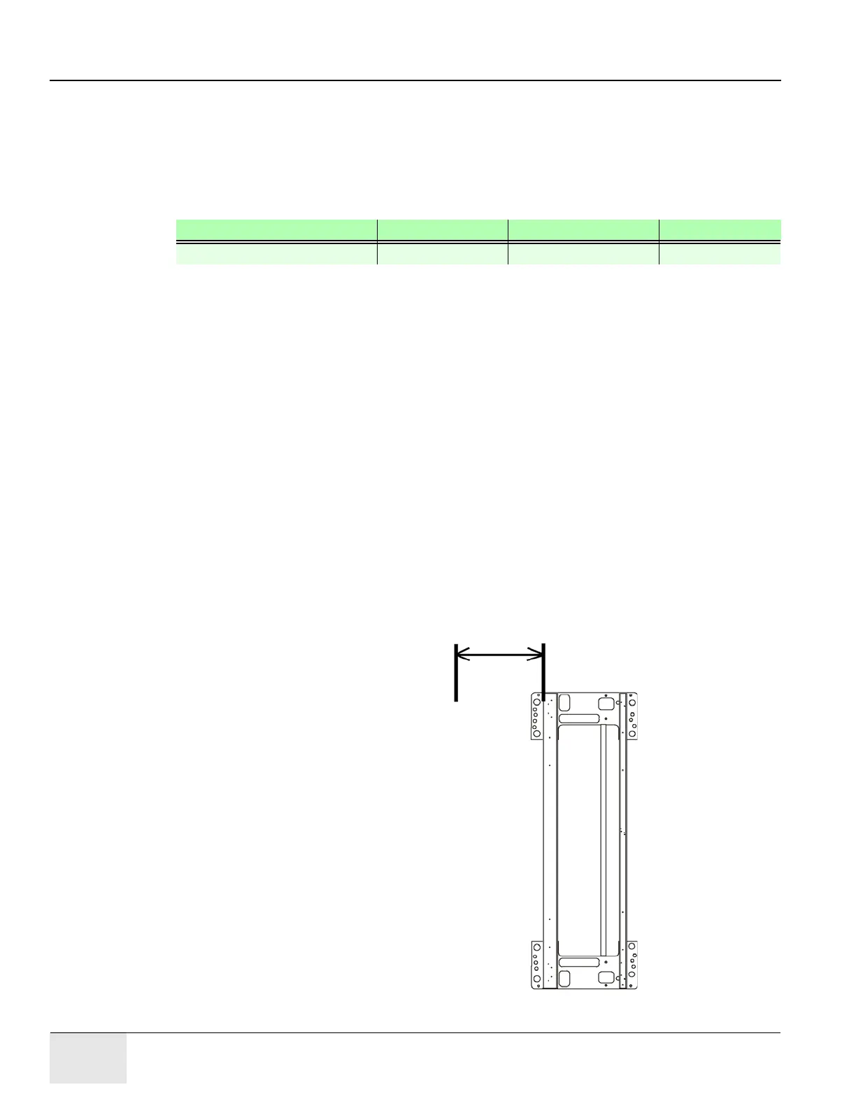
1.) Draw a reference line of 673 ± 6 mm (26.5" ± 0.25")position from Gantry Base on the floor as
shown in the Figure 1-25. This line should be parallel to the gantry. In a later section, you will
move the table against the 673 mm (26.5") mark.
Figure 1-25 Draw Reference Line
Required Persons Preliminary Reqs Procedure Finalization
2 (FE or mechanical supplier) 1.5 hours labor on-site
Draw this line on the floor.
Gantry Base
673 ± 6 mm (26.5" ± 0.25")

 Loading...


