GE COMPANY
DIRECTION 5472001-1EN, REVISION 6OPTIMA CT680 SERIES AND OPTIMA CT670 INSTALLATION MANUAL
Chapter 2 - Power, Ground & Interconnect Cables Page 109
2 – Install Power
Scan Monitor
- Video cable from Console Host PC DP to Monitor DVI
- Power cable from Console AC Box J10
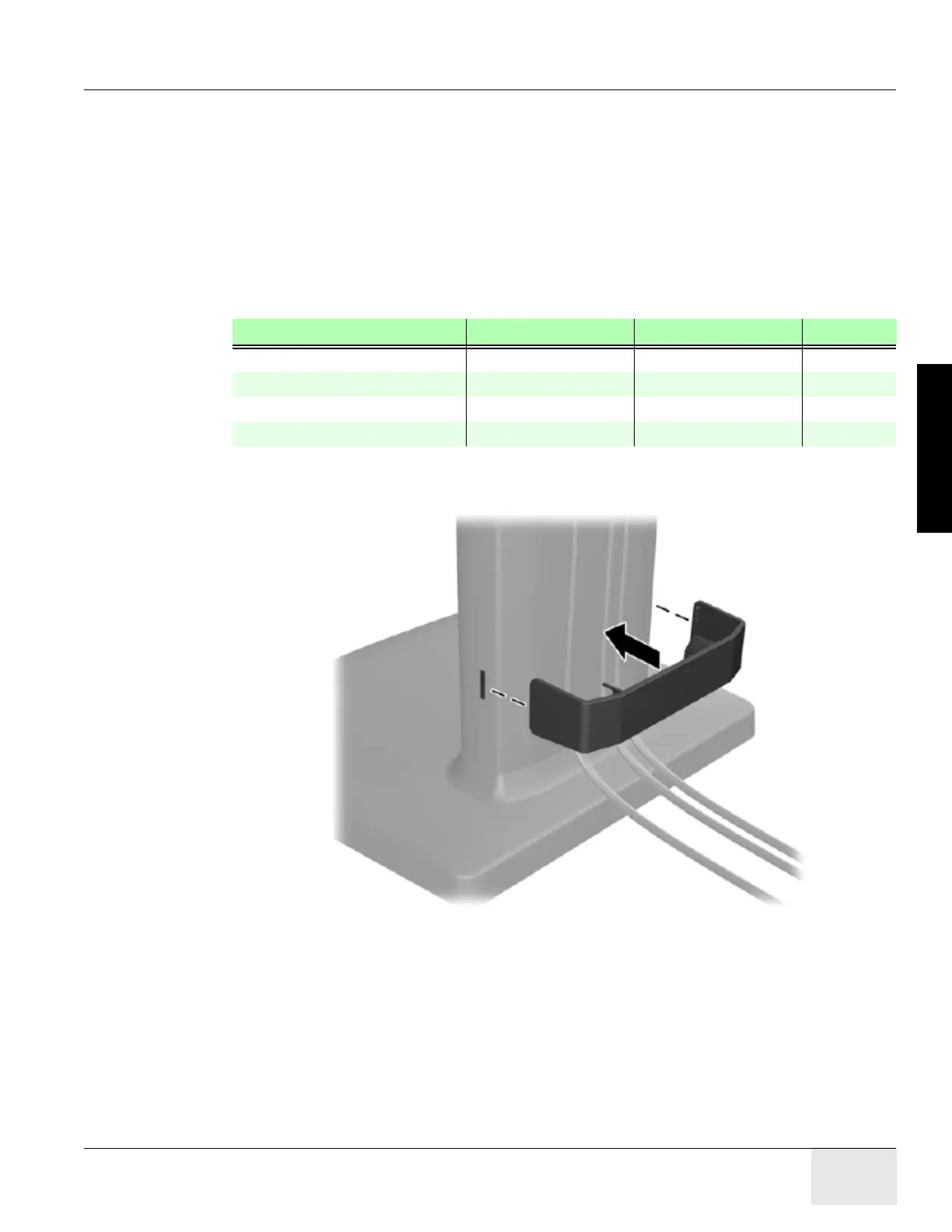
- Route through the cable keeper
Display (Image) Monitor
- Video cable from Console Host PC DVI to Monitor D-SUB (VGA)
- Power cable from Console AC Box J9
- Route through the cable keeper
Figure 2-11 Cable Routing and Keeper
3.3.3 LCD Video Monitor Setup
Detail LCD video monitor setup please refer to Service Methods→
Align,Setup,Cals
→Console
→LCD Video Monitor Setup.
DESCRIPTION PART NUMBER CABLE LENGTH QTY
Scan Monitor Power Cable 5432953-4 3050 mm 1
Scan Monitor Video Cable 5408703 3000 mm 1
Display Monitor Power Cable 5432953-3 3050 mm 1
Display Monitor Video Cable 5332107-2 3000 mm 1
Table 2-9 Monitor Cables

 Loading...


