GE COMPANY
DIRECTION 5472001-1EN, REVISION 6OPTIMA CT680 SERIES AND OPTIMA CT670 INSTALLATION MANUAL
Chapter 1 - Position Subsystems Page 43
1 – Pos. Subsystems
Section 6.0 Level the Gantry
6.1 Time and Personnel
6.2 Tools and Test Equipment
• Standard Install Tool Kit
• Install Support Kit
• GE Site Print
• Gantry Adjuster Tool, P/N 2107863
• Spanner Wrench, P/N 2110003
• PPE
6.3 Procedure
The gantry uses 2 bubble levels that are permanently mounted to machined surfaces on the
stationary base to tell when it is level.
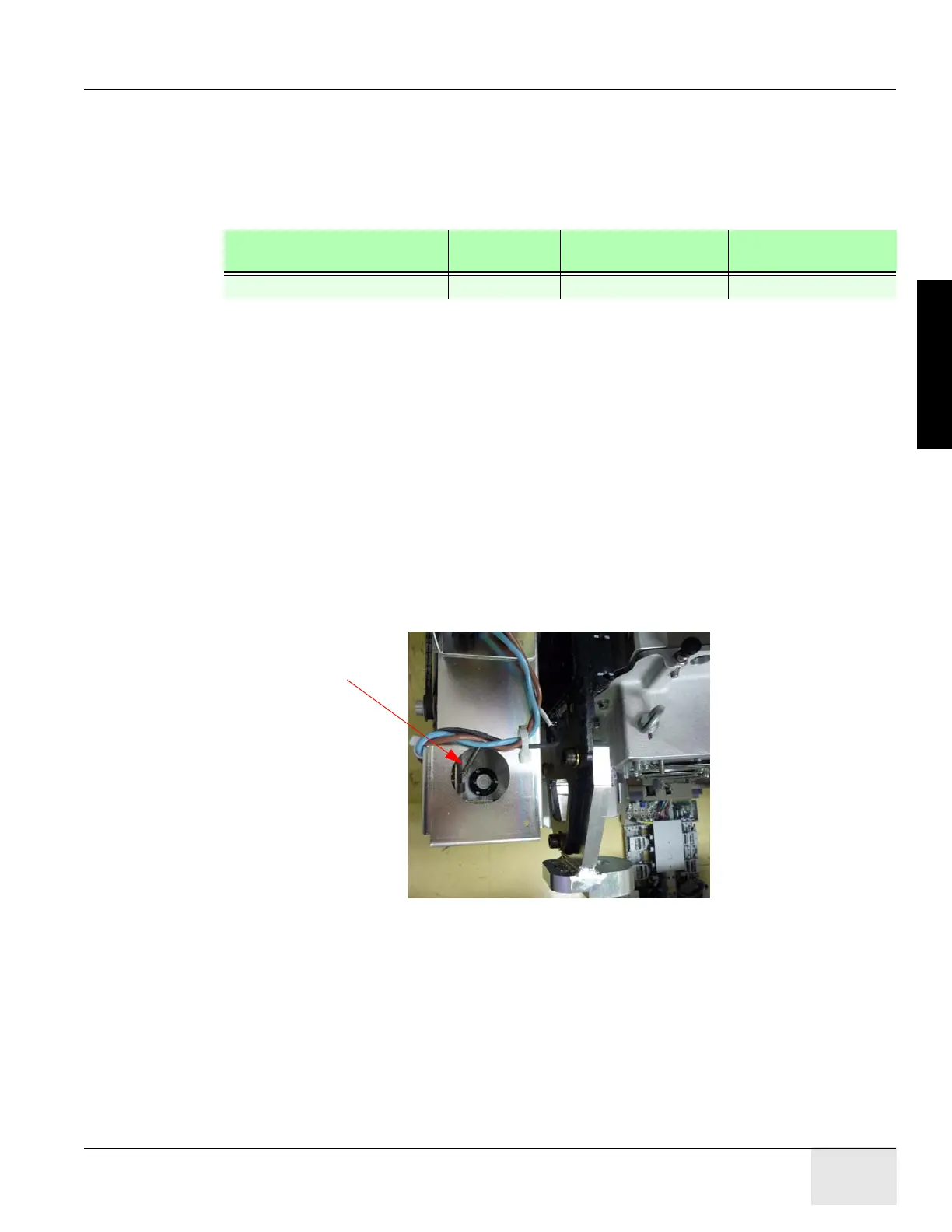
Figure 1-10 Gantry Bubble Level
Bubble levels are located on both ends of the gantry stationary base. They’re located on the
stationary base near a point where the rotating structure pivots mount to the base structure. (See
Figure 1-10.) The gantry is properly leveled when the bubble is centered. (See Figure 1-12, on
page 45).
Required Persons Preliminary
Reqs
Procedure Finalization
2 (FE or mechanical supplier)

 Loading...


