GE COMPANY
DIRECTION 5472001-1EN, REVISION 6OPTIMA CT680 SERIES AND OPTIMA CT670 INSTALLATION MANUAL
Page 44 Section 6.0 - Level the Gantry
1.) Loosen all adjuster lock rings (use a spanner wrench or large channel lock pliers).
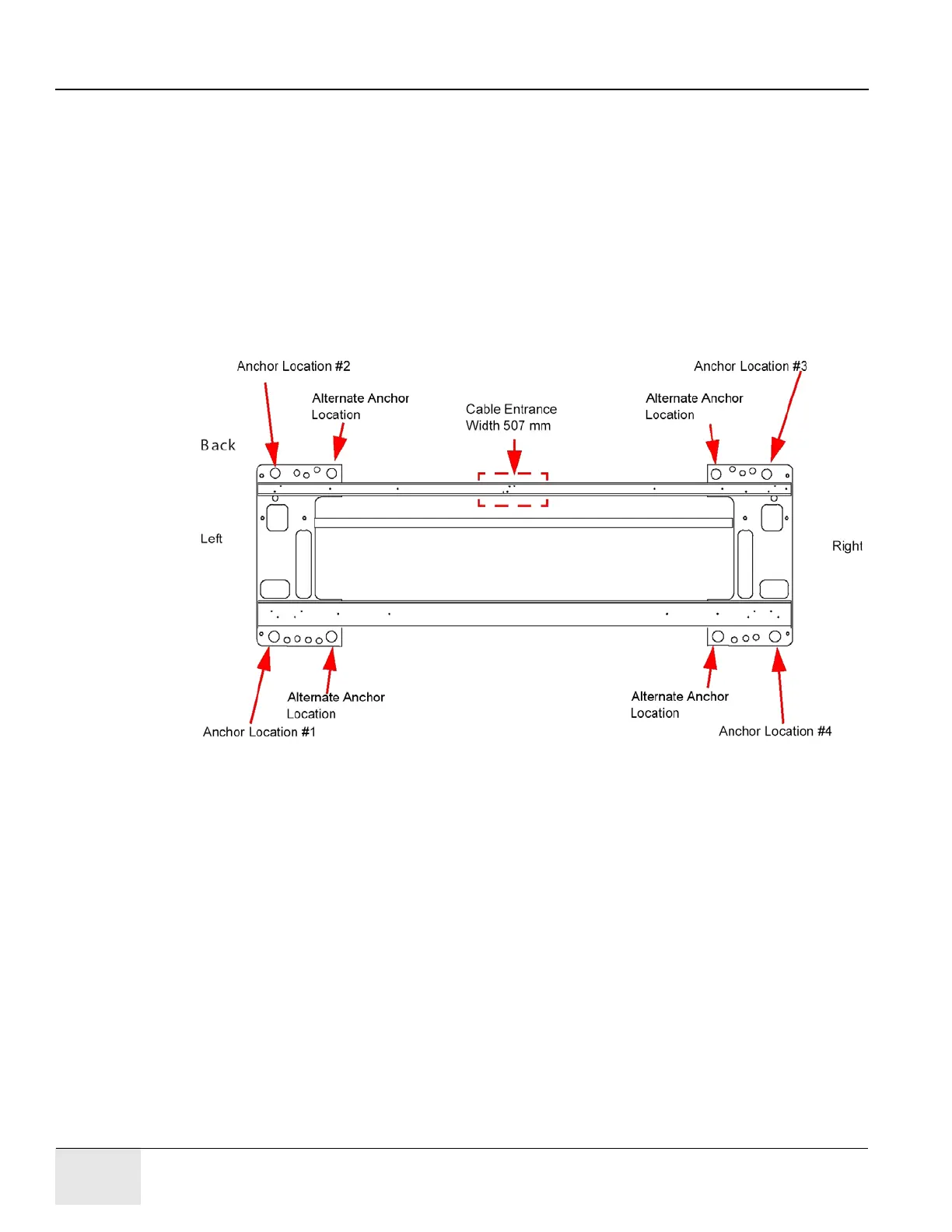
2.) Systematically turn each of the gantry’s adjusters (locations 1, 2, 3 and 4 in Figure 1-11) until
both bubble levels are centered left to right and front to back.
- Begin by turning each adjuster no more than 1 turn at a time.
- Use the adjuster tool, 1-1/8” socket, and the ½" drive ratchet to turn each adjuster.
(Refer to Figure 1-5, on page 40.)
Systematic Procedure for Leveling gantry follows:
a.) Level the left side from front to back by turning adjusters #1 and #2.
b.) Level the right side from front to back by turning adjusters #3 and #4.
c.) Level the side (right or left) that is higher with respect to the other side. Turn both adjusters
on a side equally until that side is level. The side should now also be level.
Figure 1-11 Gantry Base "Adjuster" Locations - Top View
3.) When the bubble levels are centered (Figure 1-12), each of the four (4) leveling pads should
be carrying a portion of the gantry weight. Distribution of the gantry weight prevents the base
frame from rocking during normal operation. DO NOT leave any adjuster un-loaded or
floating.

 Loading...


