GE COMPANY
DIRECTION 5472001-1EN, REVISION 6OPTIMA CT680 SERIES AND OPTIMA CT670 INSTALLATION MANUAL
Page 170 Section 1.0 - Gantry Cover Removal
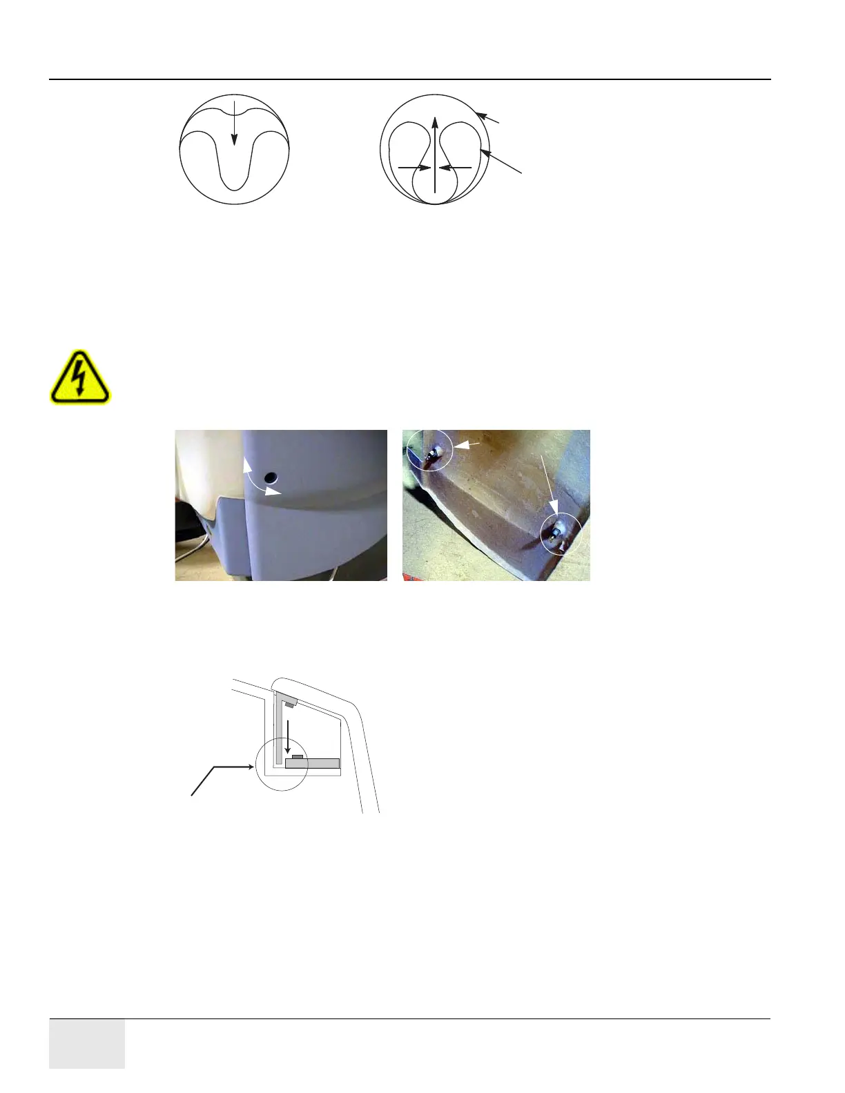
Figure A-1 Scan Window Removal
1.3.2 Side Cover Removal
1.) If removing side cover in preparation for front cover removal, move the table to its lowest
position before powering off gantry.
CAUTION Shock Hazard
Voltage Present
No service on left side while energized.
2.) Use an 8mm Hex wrench to unlatch the side cover from the front cover. See Figure A-2.
Figure A-2 Side Cover Latches
3.) Remove the right side cover by lifting it upward to release the two (2) latches, located on the
top edge of the cover. See Figure A-3. Once removed, the service switches should be
exposed.
Figure A-3 Side and Top Cover Clasp
4.) Turn OFF the three (3) main power switches (HVDC, 120VAC, and Axial Drive) on the Service
Opening in Gantry Covers
Scan Window
SCAN WINDOW IN POSITION REMOVE SCAN WINDOW
Inside view of latches
Turn the latch
¼ turn. The
cover latches
and unlatches
from the front
cover.
Side Cover
Top Cover
Metal Tab on "side" cover
fits behind bracket on "top" cover

 Loading...


