GE COMPANY
DIRECTION 5472001-1EN, REVISION 6OPTIMA CT680 SERIES AND OPTIMA CT670 INSTALLATION MANUAL
Page 50 Section 8.0 - Install Gantry Alignment Laser and Bracket
Section 8.0 Install Gantry Alignment Laser and Bracket
8.1 Time and Personnel
8.2 Tools and Test Equipment
• Standard tool kit
• Laser Alignment kit (p/n 5272090)
• 9" level
• Tape measure
• Masking tape
8.3 Procedure
NOTICE Use caution while removing the gantry scan window.
1.) Rotate the gantry by hand until the collimator face plate is at the 5 o’clock position.
Note: With power OFF, the gantry movement is tight.
DO NOT pin the gantry during this alignment process.
2.) Remove the Gantry side, top, front, and rear covers.
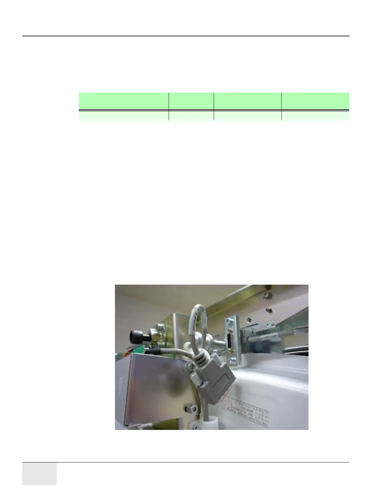
3.) Disconnect two connectors from top of the bore cover.
Figure 1-18 Disconnecting two connectors
Required Persons Preliminary
Reqs
Procedure Finalization
2 (FE or mechanical supplier)

 Loading...


