GE COMPANY
DIRECTION 5472001-1EN, REVISION 6OPTIMA CT680 SERIES AND OPTIMA CT670 INSTALLATION MANUAL
Chapter 1 - Position Subsystems Page 51
1 – Pos. Subsystems
4.) Remove two (2) bottom bore cover screws and loosen the top bore cover screw.
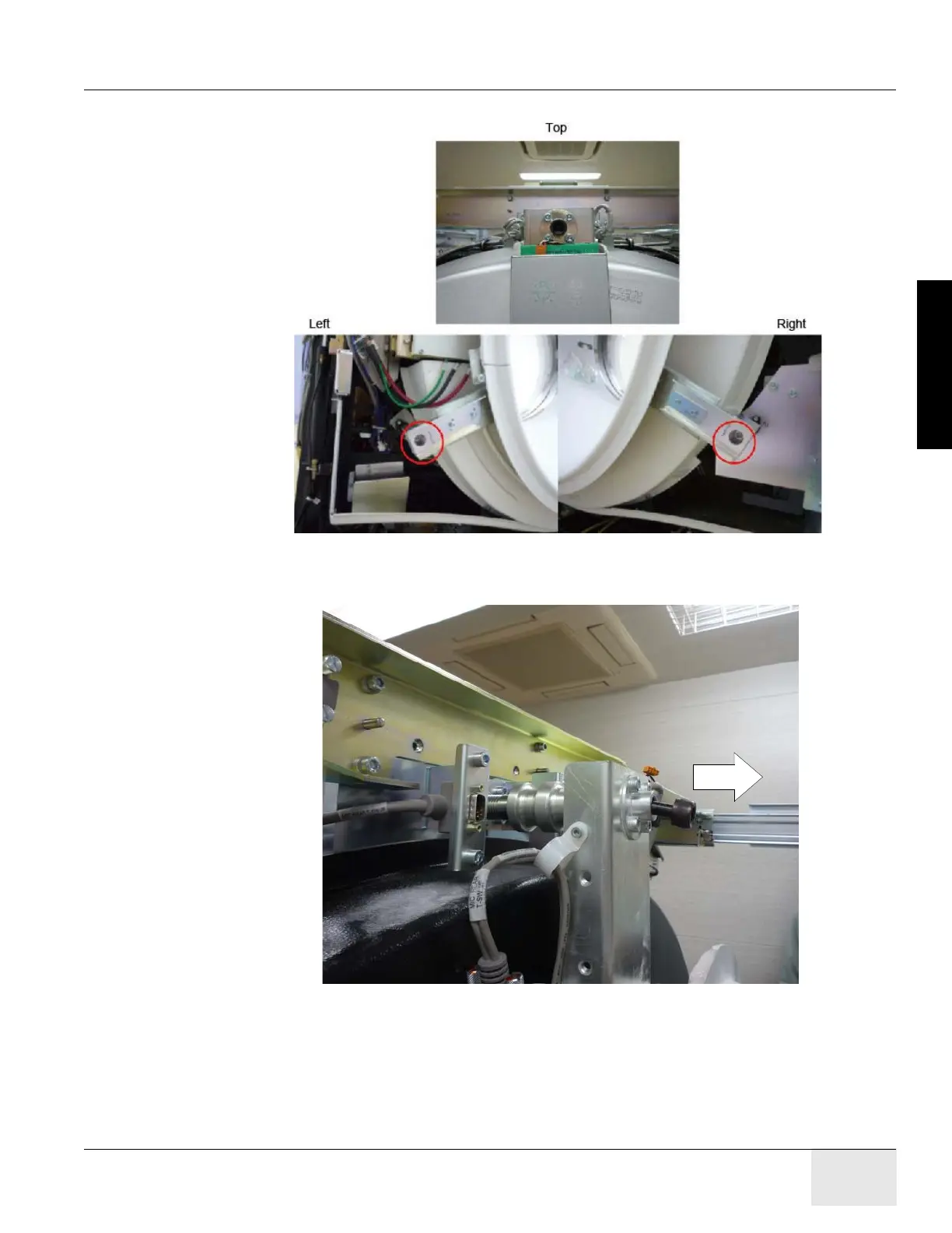
Figure 1-19 Bore Cover Screws
5.) Slide the bore cover about 5 cm (2 in.) so that the laser tool can be attached.
Figure 1-20 Sliding Bore cover backward
6.) With the Gantry top, rear, and bore covers removed, locate the two M10 bolt holes as shown
in Figure 1-21. These bolt holes are used to attach the laser tool to the gantry.
- The bolts can be installed using an 8 mm Allen wrench. Be careful not to bump the
alignment light; the mounting space is tight near the alignment light. Tighten bolts until
both are snug.

 Loading...


