GE COMPANY
DIRECTION 5472001-1EN, REVISION 6OPTIMA CT680 SERIES AND OPTIMA CT670 INSTALLATION MANUAL
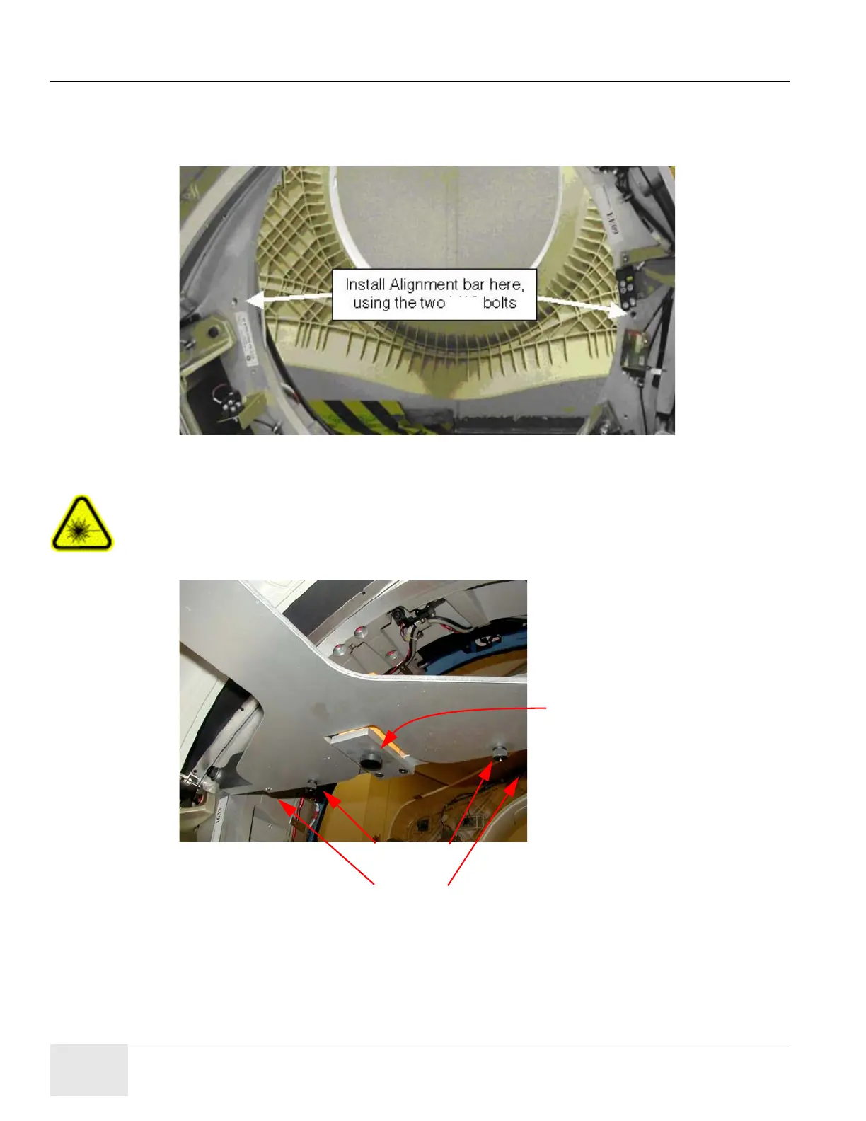
Page 52 Section 8.0 - Install Gantry Alignment Laser and Bracket
- Do not drop bolts or the bar on the collimator faceplate. Attach the bar as shown in
Figure 1-21.
- Using a minimum 223 mm (9 in.) level placed on the attached bar, level the bar by rotating
the gantry.
Figure 1-21 Alignment Bar Installation Location
CAUTION Potential for injury.
DO NOT look into the laser.
Use appropriate safety procedures when working with lasers.
7.) Attach the laser centering plate onto the laser mounting bar as shown in Figure 1-22. The plate
is attached from under the alignment bar using two fixed locators and two thumb screws.
Figure 1-22 Attach Laser Center Plate
8.) When done, insert the laser and turn on the laser using the controls on the back.
If the laser is loose when mounted, use a 2 in. piece of Velcro loop (fuzzy) section and attach
it to the alignment plate over the attachment screw. Remount the laser and it should fit snugly
without moving.
Thumb screws
Alignment tabs (right tab not shown)
Laser
Mounting
Screw

 Loading...


