GE COMPANY
DIRECTION 5472001-1EN, REVISION 6OPTIMA CT680 SERIES AND OPTIMA CT670 INSTALLATION MANUAL
Chapter 1 - Position Subsystems Page 67
1 – Pos. Subsystems
c.) Tighten adjustment knob.
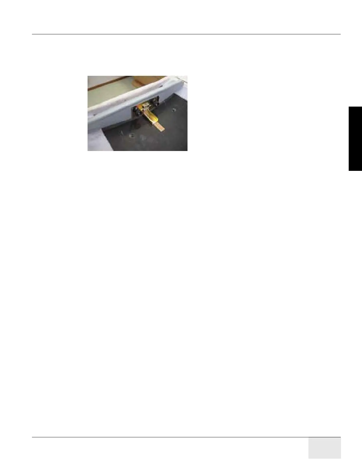
2.) Install the rear table laser alignment which has a cross target to the back of the cradle.
a.) Loose adjustment knob to make the slot plate free.
b.) The slot of the tool should be over the cradle center-line. See Figure 1-46.
Figure 1-46 Rear Table Laser Alignment
c.) Tighten adjustment knob.
3.) Check that table base is centered over the table center line, and the base is on the 564mm
line made on the floor, see Figure 1-38.
10.3.4 Level and Center the Table to the Gantry
10.3.4.1 Conditions
• Before you start, turn on the laser and check that the beam is still on the mark placed on the
wall. If not, reset the laser.
• If the mark is not present, use a measuring tape and place a 102 mm (4 in.) piece of masking
tape on the cradle at the 1000 mm and on the laser line.
• Table base to cradle alignment location is 1005 mm from the center of cradle to the floor.
10.3.4.2 Specifications
• Table cradle must be level in all directions (centered within the lines on a Johnson Professional
level).
• All table adjusters should be preset to 20 mm (3/4 in.) down from the table base to make
adjustment easier. Based on floor levelness and your experience, a different preset height may
work better. One thread must be showing above all locking rings when leveled.
• Table cannot be higher than 1005 mm from floor to cradle.

 Loading...


