GE COMPANY
DIRECTION 5472001-1EN, REVISION 6OPTIMA CT680 SERIES AND OPTIMA CT670 INSTALLATION MANUAL
Page 198 Appendix D - Remote Monitor Option Console Wiring
USE PROPER LOCKOUT/TAGOUT PROCEDURES AT THE “MAIN”
DISCONNECT
BEFORE WORKING ON EQUIPMENT.
CAUTION Do not apply power to the system until all work has been completed and all covers are in
their proper place.
Before performing any of the installation procedures described in this section, do the following:
1.) After the customer has saved all information: Power down system.
2.) Perform LOTO at A1 breaker.
3.) Remove the front console cover, using a screwdriver for the two quarter-turn screws located
on the console bottom. Screws may differ for your console type.
4.) Locate the console power panel.
5.) Remove the console back cover if required to install the splitter.
2.2 Install 4-Way Splitter
Follow the steps below to install the 4-way splitter.
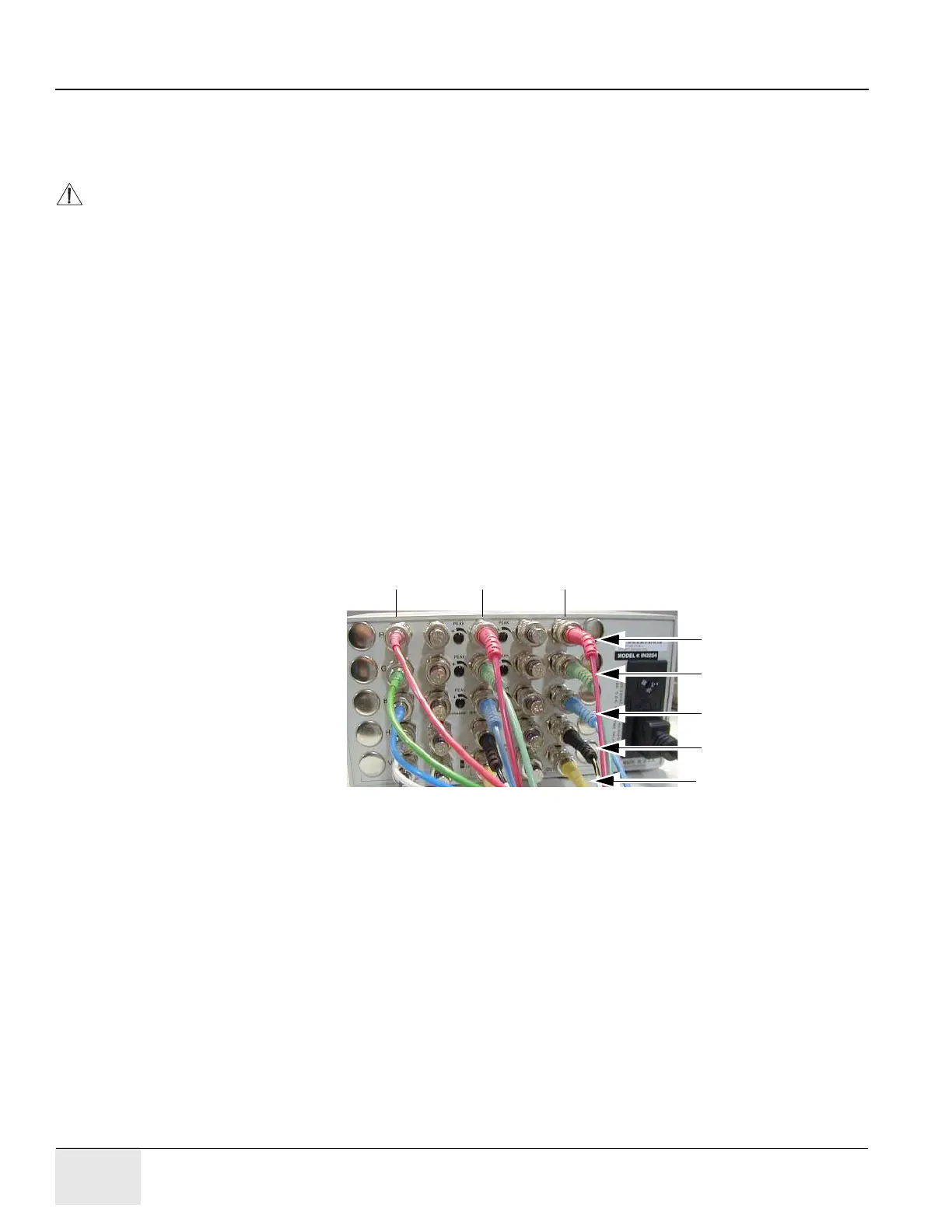
Figure D-2 shows splitter connections when completed.
Figure D-2 4-Way Splitter Connections, Completed
Note: The video cable connections shown in Figure D-2 apply to all 4-way splitters, even if the splitter
itself appears different from that shown.
Red
Green
Blue
Black (H Sync)
Yellow (V Sync)
video Out to LCD
Image Monitor
Video Out to In-
Room Monitor
Video In
from HP

 Loading...


