GE COMPANY
DIRECTION 5472001-1EN, REVISION 6OPTIMA CT680 SERIES AND OPTIMA CT670 INSTALLATION MANUAL
Appendix A – Gantry Cover Removal and Dolly Setup Page 181
A - Covers
e.) Place the Display in the bracket on the right side of the gantry. (see Figure A-23)
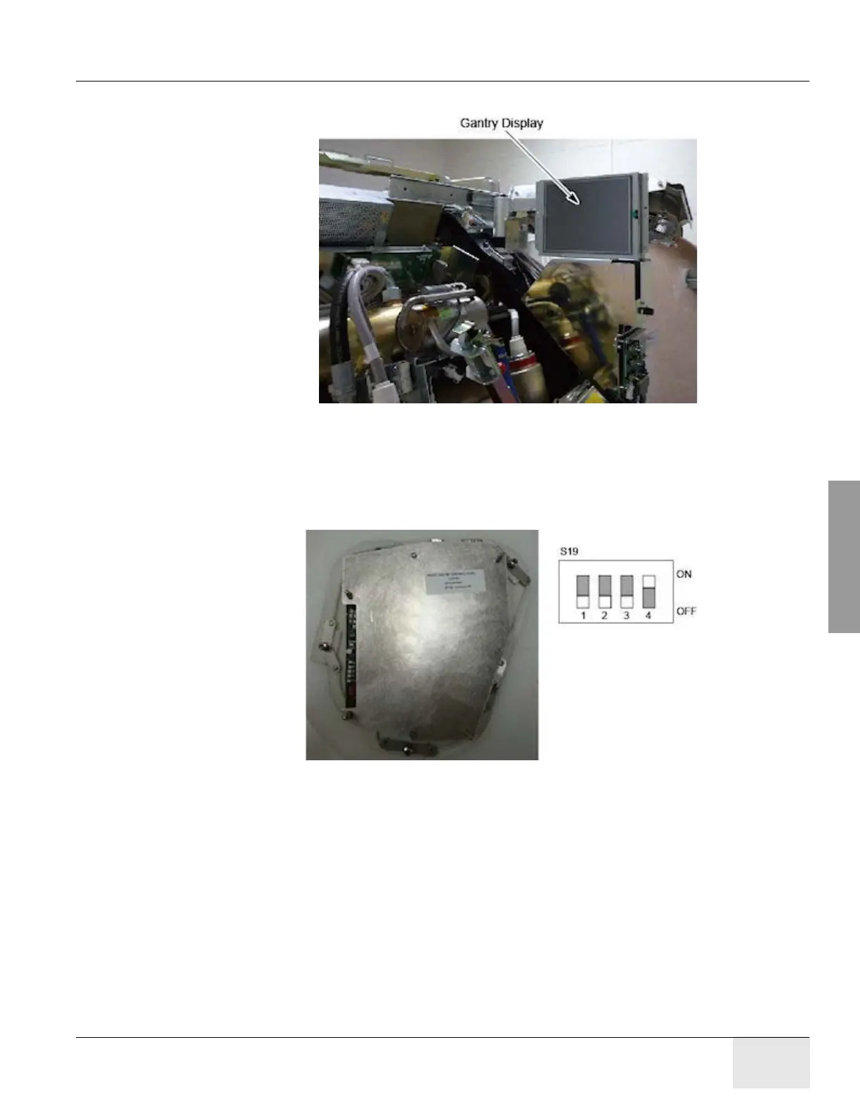
Figure A-23 Gantry Display Service Mounting Location
12.) Remove right gantry control assemblies, and place it into its service position.
a.) Loose five (5) screws that fasten the control panel to the cover. See Figure A-24. Keep
one hand on the control panel at all times to prevent it from dropping to the floor.
b.) Set dip switch s19-4 to ON position.
Figure A-24 Dip Switch S19 - 4 Setting

 Loading...


