ADL300 • Appendix 139
1.3 Process Data Channel Control
This function allows to allocate the drive parameters or application variables to the Process Data Channel data.
As for the CANopen protocol, the PDC is performed via the PDO messages (Process data Object).
The CANopen protocol uses a number of words for the Process Data Channel (abbr. PDC Process Data Channel ), which
can always be set.
The eldbus Process Data Channel conguration is the following:
Data 0 Data... Data n
The drive can both read and write the Process Data Channel data.
A datum can be made both of 2 and 4 bytes. The word “data” refers to any quantity of bytes included between 0 and 16, if
the byte total number required is not higher than 32.
Example:
It is possible to have:
- from 0 to 16 data with 2 bytes
- 1 datum with 4 bytes + from 0 to 14 data with 2 bytes
- 2 data with 4 bytes + from 0 to 12 data with 2 bytes
...
- 8 data with 4 bytes
The data exchanged via the PDC can be of two types:
- drive parameters
- variables of an MDPlc application. The use of the MDPlc variables is described in par. 1.3.1 and 1.3.2.
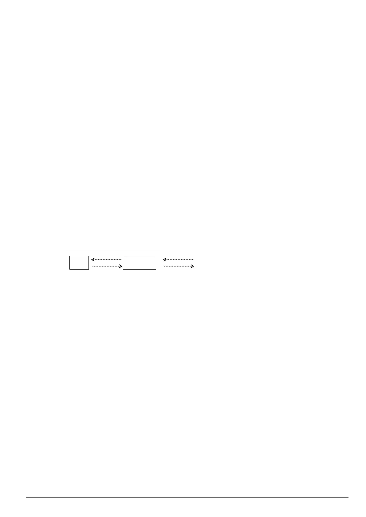
The master writes the data dened as PDC input and reads the data dened as PDC output.
PDC
CANopen
interface
Drive
Input
Output
PDO
PDO Tx
1.3.1 PDC Input Conguration (FB XXX MS Parameter)
Data exchanged in RPDOs are congured using the parameters in the COMMUNICATION->FIELDBUS M2S menu.
PAR 4030 Fieldbus M->S2 ipa = IPA of the parameter to be exchanged
Must contain a valid IPA corresponding to the parameter to be written or 0 if sys (PAR 4032...4172 Fieldbus M->Sn sys )
is Fill or Mdplc; the parameter PAR 4020 Fieldbus M->S1 ipa must be assigned to the Lift Wdef Input, while the parameter
PAR 4022 Fieldbus M->S1 sys must be set on Mdplc16
By selecting the corresponding enum PAR 4034 Fieldbus M->S2 mon for src type parameters (Source), the value of the
parameter 4030 is automatically set at the IPA of the src.
For src type parameters with an FB type dierent from 0, the data arriving on the eldbus is not written in the enum selec-
tion, but directly in the mon associated with the src.
If it contains a valid IPA and is forced to 0, the corresponding sys parameter takes on the Fill value (16 or 32 in relation to
that shown before), ensuring that the structure of the exchanged data area is not modied.
PAR 4032 Fieldbus M->S2 sys = format of the data to be exchanged
This parameter is automatically changed to the recommended value when the corresponding PAR 4030...4170 Fieldbus
M->Sn ipa is changed. The automatic value can be changed by the user, however, the permitted values depend on the
parameter.
Data mapping in PDOs is performed on the basis of the data format set in Fieldbus M->Sn sys according to the following
rules:
– PDOs are lled starting from RPDO1
– When the PDO contains 4 words it is full and the next RPDO is lled with a maximum of 4 PDOs
– 32-bit data (long or oat) cannot be split among PDOs, they must be placed inside the PDO (an alarm is generated)
– PDOs containing fewer than 4 words can be created, using Fieldbus M->Sn dest= None but assigned (Fieldbus
M->Sn sys other than Not Assigned, Fill16 or Fill32) after an assigned datum.
(N.B.: if assigned as Fill16 or Fill32, the datum is included in the PDO anyway)
– At the rst Fieldbus M->Sn sys = Not Assigned parameter the PDOs are complete. The size of the last PDO thus
depends on the data that have been assigned.

 Loading...


