ADL300 • Functions description and parameters list 27
5.4 – MECHANICAL DATA
The parameters described in this menu are used to dene the mechanical and physical features of the system.
Mechanical constants
The mechanical constant denes the ratio between motor rpm and distance travelled by the cabin.
The ConstMech can be calculated in two ways, depending on which conversion method is used.
- Directly: Mechanical constant = System speed/(Full scale speed/60)
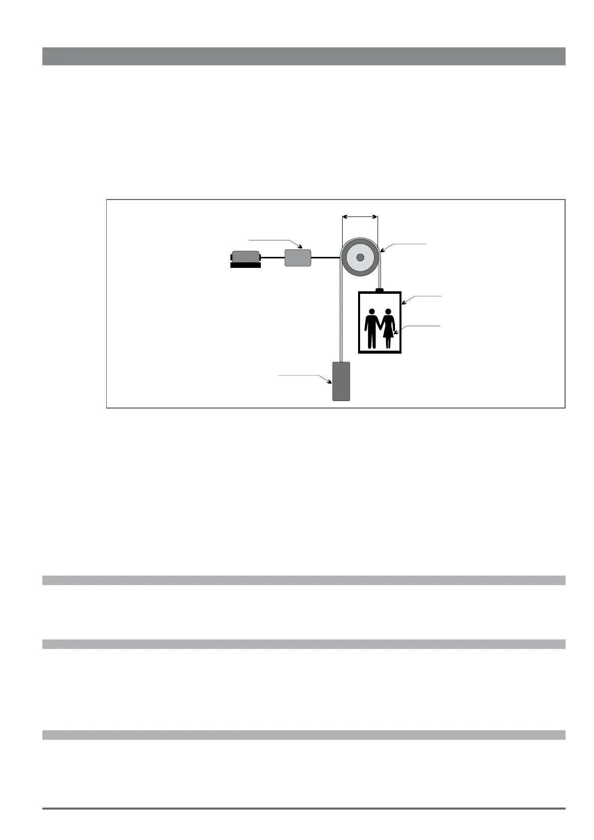
- Mechanical data: Mechanical constant = (π *Pulley diameter)/Reduction gear ratio
Pulley
Motor
Gearbox
Pulley diameter
Rope weight
Car weight
Load weight
Counter weight
Gearbox ratio
The mechanical constant is calculated when the drive is turned on and re-calculated each time one of the parameters used to deter-
mine this value is modied (Mechanical calc mode, Full scale speed, Contract speed, Pulley diameter, Gearbox ratio).
The method used to calculate the mechanical constant can be selected regardless of the control mode (SSC, Flux vector OL, Flux
vector CL, Synchronous) or the unit of measure to be used.
Weights and inertia
Entering the mechanical features of the system makes it possible to calculate the total inertia applied to the motor.
After modifying these parameters the calculated inertia value is automatically saved in the “Inertia comp” parameter to enable cor-
rect inertia compensation.
The value of the inertia that can be entered in the “Inertia“ parameter in the “16 - SPEED REG GAINS” menu is displayed to calcu-
late the speed loop parameters more accurately. This operation is performed automatically when PAR 11162 Calc spd reg gain is
enabled.
Menu PAR Description UM Type FB BIT Def Min Max Acc Mod
5.4.1 11006 Contract speed m/s FLOAT 0.5 0 10 RW FVS
Represents the speed of the system. It is also used to calculate the mechanical constant. The cabin speed in m/s is as-
sociated with the full scale speed (par. 628) to obtain the conversion factor (m/rpm).
Menu PAR Description UM Type FB BIT Def Min Max Acc Mod
5.4.2 11008 Mechanical calc mode INT16 0 0 1 ERW FVS
Setting of the method for calculating the unit of measure, depending on the speed of the cabin and of the motor (Direct
method) or according to the mechanical ratios (Mechanical data method).
0 Direct method
1 Mechanical data
Menu PAR Description UM Type FB BIT Def Min Max Acc Mod
5.4.3 11010 Gearbox ratio FLOAT 90 ERW FVS
Setting of the ratio between the speed of the motor and of the pulley.

 Loading...


